PRIMERGY PRIMERGY N800 Server System Xenia Fierley Fujitsu Siemens Computers GmbH Primergy 81730 München e-mail: email:manuals@fujitsu-siemens.com Tel.
Comments… Suggestions… Corrections… The User Documentation Department would like to know your opinion on this manual. Your feedback helps us to optimize our documentation to suit your individual needs. Fax forms for sending us your comments are included at the back of the manual. There you will also find the addresses of the relevant User Documentation Department Copyright and Trademarks Copyright © 2001 Fujitsu Siemens Computers GmbH. All rights reserved.
Introduction Important notes Installing the server Preparation for use and operation Configuration software and utilities Property and data protection Troubleshooting and tips System expansions SCSI configurations Reference section and index
Contents 1 1.1 1.2 1.3 1.4 1.5 1.6 Introduction . . . . . . . . . . . . . . . . . Features . . . . . . . . . . . . . . . . . . . Target group . . . . . . . . . . . . . . . . . Summary of contents . . . . . . . . . . . . Notational conventions . . . . . . . . . . . User-friendly documentation – verified quality Technical data . . . . . . . . . . . . . . . . . . . . . . . . . . . . . . . . . . . . . . . . . . . . . . . . . . . . . . . . . . . . . . . . . 2 2.1 2.2 2.3 2.4 2.5 2.6 2.7 2.
Contents 4.4 4.4.1 4.5 Configuring the server and components . . . . . . . . . . . . . 38 Changing the switch settings . . . . . . . . . . . . . . . . . . . 39 Cleaning the server . . . . . . . . . . . . . . . . . . . . . . . . 43 5 5.1 5.2 5.3 5.3.1 5.3.2 5.3.3 5.3.3.1 5.3.3.2 5.3.3.3 5.3.4 5.3.4.1 5.3.4.2 5.3.4.3 5.3.4.4 5.3.5 5.3.6 5.3.6.1 5.3.6.2 5.3.6.3 5.3.7 5.3.8 5.4 5.4.1 5.4.2 5.4.2.1 5.4.2.2 5.4.2.3 5.4.2.4 5.4.3 5.4.4 5.4.5 Configuration software and utilities . . . . .
Contents 7.5 7.6 7.7 7.8 7.9 7.10 7.11 7.12 7.13 No screen display or display drifts . . . . . No mouse pointer displayed on the screen Floppy disk cannot be read/written . . . . Time and date are not correct . . . . . . . System will not boot . . . . . . . . . . . . Drives are reported as “dead” . . . . . . . Added drive reported defective . . . . . . Error messages on the screen . . . . . . . Error messages on the LCD display . . . . . . . . . . . . . . . . . . . . . . . . . . . . . . . . . . . . . .
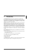
1 Introduction The PRIMERGY N800 system server is an enterprise server with 8-way processing power and offers highest performance by using the Intel profusion technology. It is easy to integrate and can easily satisfy the needs of a variety of high-performance applications such as, for example, use as a network server, multiuser server system or large database. PRIMERGY N800 server systems offer a high level of data security and availability through highly developed hardware and software components.
Features 1.1 Introduction Features Processors and Memory The server can accommodate up to eight Intel Pentium III Xeon™processors with a clock frequency of 700 MHz or 900 MHz. 1 MB and 2 MB second level cache are available. The 700 MHz or 900 MHz processors are mounted on „Palmetto mezzanine“ carrier boards. V CAUTION! In order to prevent a damage of the processors, pay attention that the processors are mounted on the corresponding carrier boards only.
Introduction Features Power supply The server is equipped with three power supplies. This ensures a power supply redundancy. If a defect occurs in one unit, the other units ensures unimpaired further operation. The defective power supply unit can be replaced during operation (hot-plug power supply). Cooling The server contains two independent cooling subsystems: – The upper system for cooling the system board, the I/O board and the upper part of the control panel.
Features Introduction Server management Server management is implemented with the aid of the supplied ServerView software and PDA (Prefailure Detection and Analyzing) technology from Siemens. The PDA analyzes and monitors all components relevant to system reliability, thus enabling early detection of overload situations and appropriate counter-measures. ServerView enables the management of all PRIMERGY servers in the network via a central console.
Introduction Target group Service and Support The PRIMERGY N800 is service-friendly and modular (compute node housing), thus enabling quick and simple maintenance. With the optional Remote Test and Diagnosis System RemoteView, long-distance maintenance and service (remote) can also be performed. Other features ● year 2000 support ● 3 years guarantee for the system unit ● 5 years spare parts supply ● take-back guarantee of old systems 1.
Summary of contents 1.3 Introduction Summary of contents This manual describes the PRIMERGY N800, its installation and configuration, and how to install extensions/upgrades.
Introduction Notational conventions ● System expansions This chapter describes in more detail how you can expand your system using various components. It also explains how to replace defective components. ● SCSI configurations This chapter explains the SCSI-IDs for the hard disk drives and internal SCSI configurations. 1.4 Notational conventions italic type Identifies commands, menu items, names of buttons, options, variables, file names, path names and input within the body of the text.
User-friendly documentation – verified quality 1.5 Introduction User-friendly documentation – verified quality As part of its efforts to further improve the information provided for users, the editorial department responsible for this manual has been independently audited to verify its high standards of quality of the documentation. This audit was carried out by TÜV PRODUCT SERVICE GmbH.
Introduction 1.6 Technical data Technical data Electrical data Rated voltage range 100 V - 120 V 200 V - 240 V (auto sense) Rated voltage tolerance +6 % / -10 % Frequency 50 Hz / 60 Hz Rated current at 100V - 120 V 12 A Rated current at 200V - 240 V 7A Effective power 1247 W Apparent power 1271 VA Heat emission 4014 kJh Building fuse 16 A Protection class I Dimensions and weight Height (mm) 312 (seven height units) Width (mm) 445 Depth (mm) 712 Weight (kg) max.
Technical data Introduction Standards Product safety and ergonomics IEC 60950 (DIN EN 60950), UL 1950, CSA 950, NEMKO Electromagnetic compatibility Interference emission EN 55022, Class A; FCC part 15, Class A Interference immunity EN 50082-1 CE certification Low voltage directive LVD 73/23/EEC EMC Directive 89/336/EEC Certification GS, CSA NRTL/C, CB Certificate Noise level (ISO 9296) Operation Idle Sound power level (LWAd) max. 5,5 B max. 4,8 B Operating sound pressure level (LpAm) max.
2 Important notes 2.1 Notes on safety In this section you will find information that you must note when using the storage subsystem. This device complies with the relevant safety standards for IT equipment, including electronic office machines, intended for use in the office environment. I Observe the safety instructions in the “Safety, Warranty and Ergonomics” manual and in the documentation for the connected PRIMERGY system.
Notes on safety Important notes V CAUTION! 12 ● The device must only be connected to a properly grounded wall outlet (the device is fitted with a tested and approved power cable). ● Make sure that the wall outlet of the building‘s wiring system is freely accessible. ● Switching off the device does not cut off the supply of power. To do this you must remove the power plugs. ● Before opening the unit, switch off the device and then pull out the power plugs.
Important notes 2.2 Electrostatic-sensitive component label Electrostatic-sensitive component label Electrostatic-sensitive components may be identified by the following sticker: Figure 1: Electrostatic-sensitive component sticker You must follow the instructions below when handling modules containing electrostatic-sensitive components: Ê Discharge static electricity from your body (for example by touching a grounded metal object) before handling modules containing electrostaticsensitive components.
CE certificate 2.3 Important notes CE certificate This device complies with the requirements of EU directives 89/336/EEC “Electromagnetic compatibility” and 73/23/EEC “Low Voltage Directive”. The device therefore qualifies for the CE (CE=Communauté Européenne) mark on the back of the device. 2.4 RFI suppression Any other devices which are attached to this product must likewise comply in respect of RFI suppression with EU directive 89/336/EEC.
Important notes 2.6 Notes on mounting in the rack Notes on mounting in the rack ● For safety reasons, at least two people are required to install the rackmounted model because of its weight and size. ● When connecting and disconnecting cables, observe the notes in the documentation for your PRIMERGY system and the comments in the “Important notes” chapter in the corresponding rack operating manual supplied with the rack.
Environmental protection 2.8 Important notes Environmental protection Environmentally friendly product design and development This product has been designed in accordance with the FSC standard for “environmentally friendly product design and development”. This means that the designers have taken into account important criteria such as durability, selection of materials and coding, emissions, packaging, the ease with which the product can be dismantled and the extent to which it can be recycled.
Important notes Environmental protection Take-back, recycling and disposal For details on take-back and reuse of devices and consumables within Europe, contact your FSC branch office/subsidiary or our recycling center in Paderborn: Fujitsu Siemens Computers Recycling Center D-33106 Paderborn Tel.
3 Installing the server 3.1 Unpacking the server V CAUTION! Observe the safety information in the chapter “Important notes” on page 11. Ask for assistance with carrying the server. You are advised not to throw away the original packaging material. You may need it again later for transportation purposes. ● Unpack all the individual parts. ● Check the delivery for damage incurred during transport. ● Check whether the delivery matches the specifications in the delivery note.
Mounting the server in the rack 3.2 Installing the server Mounting the server in the rack V CAUTION! ● Please take note of the safety information and the notes on mounting in the rack in the chapter “Important notes” on page 11. ● At least two people are needed to position the server in the rack. ● The rack may tip over if more than one heavy unit is removed.
Installing the server Mounting the server in the rack 3 x 3 x Figure 2: Mounting the carrier rails Ê Secure the two telescopic carrier rails to the left and the right inside the rack using the Allen key no. 5 supplied. Note that there is a left and right carrier rail which differ in the arrangement of the tap holes. The figure shows the left carrier rail. When mounting the carrier rails, the guide nabs of the rails next to the spring nuts must fit into the holes of the support uprights.
Mounting the server in the rack Installing the server Ê Pull the left mounted telescopic rail out as far as it will go and then mount it to the appropriate carrier with the screws. Ê Repeat this procedure for the right telescopic rail. Figure 4: Mounting the system brackets Ê Mount the system brackets on the two telescopic rails. Ê Pull the mounted telescopic rails out completely. They must click into place so that you can no longer push them back.
Installing the server Mounting the server in the rack 2 x Figure 5: Mounting the server in the rack Ê Place the server onto the two system brackets. Make sure that the metal noses grip the notches on the housing. Ê Fasten the brackets to the right and left hand sides of the server (three screws each side). The following steps require only one person. 1 Figure 6: Telescopic rails with safety springs Ê Press in the safety springs (1) on both telescopic rails.
Mounting the server in the rack Installing the server For the case, that a rack server is installed in a 19-inch rack (without cord management) an articulated cable guide must be mounted at the device: 2 1 Figure 7: Mounting the articulated cable guide Ê Insert two spring nuts in the groove of the rear right support upright at the same height with the connection cables of the server. Ê Fix the cable guide with two mounting screws on the rear right support upright of the rack (1).
Installing the server 3.3 Connecting and disconnecting cables Connecting and disconnecting cables V CAUTION! The power plug must be pulled out! Read the documentation for the external device before you connect it. Never connect or disconnect cables during thunderstorms. When disconnecting a cable, always grasp the plug. Never pull on the cable! Connect or disconnect cables in the order shown below. Connecting cables ● All affected devices must be switched off.
Routing cables 3.4 Installing the server Routing cables 19-inch Rack The cables can be fastened to the articulated cable guide without restriction. This allows the server to be removed later without further preparation. Figure 8: Cable routing Ê Connect the cables to the server and the peripheral devices. Ê Route the cables as shown in the figure. Ê Route the cables through the cable channels. Ê Fix the cables to the articulated cable guide with the cable ties (1).
Installing the server Routing cables DataCenter Rack For installing the server in the DataCenter Rack at first the cable management system must be mounted. Further informations find you in the Technical Manual of the DataCenter Rack. 2 1 Figure 9: Routing the cables in the DataCenter Rack Ê Route the cables in the articulated cable guide (1) of the cable management system and secure its using the delivered cable ties.
Connecting devices to the server 3.5 Installing the server Connecting devices to the server The ports for the devices are at the back of the server (see section “Rear view” on page 36). Which ports are available on your server depends on the PCI boards installed. The standard ports are indicated by symbols. 3.5.
Installing the server Connecting devices to the server Ê Connect the data cables to the devices and the server. I Some of the connected devices require that you install and configure special software (e.g. drivers) (see the documentation for the connected device). If you are using a separate graphics card in a slot, the graphics controller on the system board is automatically deactivated. The corresponding monitor port (SVGA) cannot be used.
Connecting devices to the server Installing the server 1 Figure 11: The PCI CAN bus controller The CAN bus connector is located on the connection panel of the CAN bus controller board (inserted into a PCI slot) on the back of the server (see figure 11 on page 30 and figure 13 on page 36). Optical fiber transmission can be used to bridge longer distances between the PRIMERGY server and the PRIMERGY S40-DF, i.e.
Installing the server Connecting the server to line voltage RemoteView (RTDS), SEMAN and the CAN bus The update of the firmware and the testing and diagnosis of the storage subsystem can only be performed via the CAN bus and using SEMAN (included on the ServerStart CD) or the optional RemoteView (remote test and diagnostics system). Refer to the RemoteView manual for more information (see “Related publications” on page 125). 3.
4 Preparation for use and operation V CAUTION! Observe the safety information in the chapter “Important notes” on page 11. 4.1 Controls and indicators 4.1.1 Control panel The control panel is located on the front of the server between the fan cage and the drive cage.
Controls and indicators Preparation for use and operation When the system is switched off, the system is switched on by pressing the ON/Off button. ON/OFF button: When the system is operating, pressing the ON/OFF button will switch off the system. I The ON/OFF button does not disconnect the server from the line voltage. To disconnect from the line voltage, remove the power plug from the power outlet. Reset button: Power-on indicator: ! ! ! Pressing the Reset button reboots the system.
Preparation for use and operation 4.1.2 Controls and indicators Indicators for the internal SCSI drives The internal SCSI drives are located on the front of the server. The status of each SCSI drive is indicated by two LEDs (see table 24 on page 91). 4.1.3 Controls and indicators for the CD-ROM drive The CD-ROM drive is located in the drive cage in the bay for externally accessible drives on the front of the server.
Controls and indicators 4.1.
Preparation for use and operation 4.2 Switching the server on and off Switching the server on and off V CAUTION! If after switching on the server there is nothing but flickering stripes on the screen, switch the server off immediately (see the chapter “Troubleshooting and tips” on page 75, section “Flickering stripes on the monitor screen” on page 77). The ON/OFF button does not disconnect the server from the line voltage.
Installing the operating system 4.3 Preparation for use and operation Installing the operating system Ê Insert the ServerStart CD and keep ready the CD of the operating system you want to install. Ê Reboot the server. Ê Follow the instructions on the screen and in the manual for the operating system. If your server is equipped with a disk array controller, please read in the appropriate manual how to configure the disk array before you install the desired system. 4.
Preparation for use and operation Configuring the server and components Switch Function Description No. Pos. 3 4 5 OFF No Password Clear Retains the password. ON Clears the current system password. Password Clear OFF NOP Reserve ON Reserve NOP OFF PHP Switch Hot-plug PCI slots, mechanical switches activated ON Hot-plug PCI slots, mechanical switches deactivated. PHP Switch Table 2: DIP switches settings 4.4.
Configuring the server and components Preparation for use and operation R e a r s id e O N 1 2 3 4 5 O F F Figure 14: I/O board/configuration switches 40 U41243-J-Z156-1-76
Preparation for use and operation Configuring the server and components Recovery Boot: This switch controls whether the system attempts to boot using the BIOS code stored in flash memory, or, if the BIOS code is corrupt, whether a recovery boot is performed by loading the BIOS code from a floppy disk into flash memory. If you want to start a recovery boot, proceed as follows: Ê Follow the procedure described in the section “Changing the switch settings”. Ê Set DIP switch 2 (see table 2 on page 38) to ON.
Configuring the server and components Preparation for use and operation CMOS Clear: This switch controls whether settings stored in non-volatile CMOS memory (NVRAM) are retained when the system is reset or whether the default settings are loaded. If you want to change the settings in NVRAM, proceed as follows: Ê Follow the procedure described in the section “Changing the switch settings” on page 39. Ê Set DIP switch 2 (see table 2 on page 38) to ON. Ê Switch the system on.
Preparation for use and operation Cleaning the server Password Clear: This switch controls whether the current password is retained or cleared when the system is reset. If you want to change the current password, proceed as follows: Ê Follow the procedure described in the section “Changing the switch settings”. Ê Set DIP switch 3 (see table 2 on page 38) to ON. Ê Switch the system on. Wait for POST to complete. This clears the current password.
5 Configuration software and utilities This chapter describes the Power-ON Self-Test (POST) and the configuration software. 5.1 Short cuts using a key combinations Use the numeric pad on the keyboard to enter numbers and symbols. Key combinations Clear memory and reload the [Ctrl]+[Alt]+[Del] operating system, i.e. system reset Save system immediately [Ctrl]+[Alt]+hotkey (set your hot-key combination with BIOS Setup.) Call BIOS Setup during POST [F2] Table 3: Key combinations 5.
Power-ON Self-Test (POST) Configuration software and utilities Ê Press [F2] to start BIOS Setup and configure the settings.
Configuration software and utilities 5.3 BIOS Setup BIOS Setup This section describes the options available for BIOS Setup. Use Setup to change the default system parameters. You can run BIOS Setup with and without the installed operating system. Setup stores most of the configuration values in battery-backed CMOS; the rest of the configuration is stored in flash memory. The configuration takes effect when you boot the system. POST uses these values to configure the hardware.
BIOS Setup 5.3.
Configuration software and utilities 5.3.2 BIOS Setup Setup menus Setup provides six main menus and a number of submenus: Pos.
BIOS Setup Configuration software and utilities The table below lists the selection options displayed on the screen after you press [F2] (start BIOS Setup). Not all the options are described since many are self-explanatory. Several of the options are only displayed for information purposes (they cannot be selected): Key [F1] [Esc] Ê Ë ÂÀ {-} [+] Ú [F9] Meaning Get help about a menu item Return to previous item. Select the previous value in a list of menu items.
Configuration software and utilities 5.3.3 BIOS Setup Main Menu Default values are in bold typeface. Menu item Option Description System Time HH:MM:SS Set the system time. To select a field, press[Tab], Í+[Tab] or Ú. Then enter a new value. If you replace the battery, the time is set to 00:00. (This is a 24-hour clock.) System Date MM/DD/YYYY Set the system date. To select a field, press[Tab], Í+[Tab] or Ú. Then enter a new value.
BIOS Setup Menu item Configuration software and utilities Option Keyboard Features Language Description Select the Keyboard Features submenu. Press Ú for options. English (US) Français Deutsch Italiano Español Select the display language for BIOS. Table 7: Main menu options 5.3.3.
Configuration software and utilities Menu item Option 32-bit I/O Disabled Enabled Transfer Standard Mode Fast PIO 1, 2, 3, or 4 Ultra DMA Disabled Mode Mode 0, 1, or 2 BIOS Setup Description Enabled allows 32-bit IDE data transfer. Selects the mode for transferring data to/from the drive. Automatic BIOS entry. Selects the Ultra-DMA mode for transferring data to/from the drive. Automatic BIOS entry. Table 8: IDE options 5.3.3.
BIOS Setup 5.3.3.3 Configuration software and utilities Keyboard Features submenu Menu item Option Description Numlock Auto On Off Activates numlock status at startup. Key Click Disabled Enabled Activates key click. Keyboard autorepeat rate 30/sec. 26,7/sec. 21,8/sec. 18,5/sec. 13,3/sec. 10/sec. 6/sec. 2/sec. Selects key repeat rate. Keyboard autorepeat delay 1/4 sec. 1/2 sec. 3/4 sec. 1 sec. Selects delay before key repeat.
Configuration software and utilities 5.3.4 BIOS Setup Advanced Menu V CAUTION! Setting incorrect values in this menu may cause your system to malfunction. Menu item Option Description Processor Serial Number Disabled Enabled Processor serial number control Reset Configuration Data No Yes Clears system configuration data. Use Multiprocessor Specification 1.1 1.4 Specifies the multiprocessor specification revision level. Some operating systems require revision level 1.1. for compatibility.
BIOS Setup Configuration software and utilities Menu item Option Description PCI Configuration Selects the PCI Configuration submenu. I/O Device Configuration Selects the I/O Device Configuration submenu. Advanced Chipset Control Selects the Advanced Chipset Control submenu. Table 11: Advanced options 5.3.4.1 (continued) PCI Configuration submenu Menu item Option Description Processor Bus 100 MHz Displays the clock speed of the Processor Bus.
Configuration software and utilities Menu item Option BIOS Setup Description PCI Slot 5 Selects PCI Mode Submenu for this PCI slot. PCI Slot 6 Selects PCI Mode Submenu for this PCI slot. PCI Slot 7 Selects PCI Mode Submenu for this PCI slot. PCI Slot 8 Selects PCI Mode Submenu for this PCI slot. PCI Slot 9 Selects PCI Mode Submenu for this PCI slot. PCI Slot 10 Selects PCI Mode Submenu for this PCI slot. Table 12: PCI configuration options 5.3.4.
BIOS Setup 5.3.4.3 Configuration software and utilities I/O Device Configuration submenu Menu item Option Serial Port A Description Configures serial port A using options: Disabled No configuration Enabled User configuration Auto BIOS or the operating system chooses configuration. 3F8 2F8 Base I/O Address 3E8 2E8 Sets the I/O address for serial port A: Interrupt Sets the IRQ for serial port A.
Configuration software and utilities Menu item Option BIOS Setup Description Base I/O Address 378h 278h 178h 3BCh Sets the I/O address for the parallel port (178 can only be set in EPP mode. Otherwise, 3BCh is available). Interrupt IRQ5 IRQ7 Sets the IRQ for the parallel port. DMA channel DMA 1 DMA 3 Selects the DMA channel for LPT port when configured for ECP mode.
BIOS Setup 5.3.4.4 Configuration software and utilities Advanced Chipset Control submenu Menu item Option Description Extended RAM Step 1 MB Selects the thoroughness of the 1 KB memory test of the extended Every location memory. BIOS defaults to the fastest test. L2 Cache Disabled Disables the secondary cache for core clock frequency/bus ratios equal to 2. Enabled Causes the secondary cache to be sized and enabled.
Configuration software and utilities 5.3.5 BIOS Setup Security Menu Menu item Option Description User password is Set Clear When you enter your user password, this option automatically changes to Set. Administrator password is Set Clear When you enter an administrator password, this option automatically changes to Set. Set user password Press Enter The user password controls the boot process (to enter a password, press Ú and follow the screen prompts).
BIOS Setup Configuration software and utilities Menu item Option Description Secure Mode Boot Disabled Enabled Starts the system in secure mode (the system is released by entering a password). Video Blanking Disabled Enabled Blanks the screen when secure mode is enabled (the system is released by entering a password). Floppy Write Protect Disabled Enabled Write-protects the floppy disk drive when secure mode is enabled (deactivate the write-protect option by entering a password).
Configuration software and utilities 5.3.6 BIOS Setup Server Menu Menu item Option Description System Management Selects the System Management submenu to change the server management features. Console Redirection Selects the Console Redirection submenu. Processor Retest No Yes Clears the previous processor status from BIOS and retests all the processors the next time the system boots. EMP Password Switch Disabled Enabled Activates the EMP password. EMP Password Selects the EMP password.
BIOS Setup 5.3.6.1 Configuration software and utilities System Management submenu Menu item Firmware SMIs Option Disabled Enabled Disabled Enabled Description Disables all firmware SMI sources. Clear Event Log Disabled Enabled Deletes the system event log. Memory Scrubbing Disabled The chipset will deliver corrected data but will not update the memory contents. Enabled The chipset will correct the memory contents when a correctable error is detected.
Configuration software and utilities 5.3.6.2 BIOS Setup Server Management Information submenu This submenu displays the system serial numbers, system part number, and server management controller revisions. No changes can be made in this menu in user mode. If you want to make changes, please consult your system administrator.
BIOS Setup 5.3.7 Configuration software and utilities Boot Menu Menu item Option Floppy Disabled Check Enabled Description Accelerates the boot process. Checks the floppy disk drive type on boot. Boot Device 1. Removable Devices Selects the search order for the types Priority of boot devices. 2. Hard Drive The operating system assigns drive 3. ATAPI CD-ROM Drive letters to the devices in the order shown. Use the Ê and Ë arrows to select a device.
Configuration software and utilities Menu item Option Pause Disabled During Enabled POST Description Starts IRTOS manually. When you hear three beeps, POST has stopped (press any key to continue). Table 21: Boot Menu options 5.3.8 BIOS Setup (continued) Exit Menu The following menu items are available on the Server menu. Select an item using the up and down arrows. Press Ú to select this option and follow the instructions.
Utilities Configuration software and utilities 5.4 Utilities 5.4.1 System Setup Utility (SSU) The System Setup Utility (SSU) is used for configuring the system under operating systems such as, for example, Open Server, Netware, Unixware 7.1.0. These operating systems are not “shared interrupt“-capable and the resources must be assigned clearly to the PCI slots /PCI add-on boards. The parameters set with the SSU take precedence over the BIOS Setup settings.
Configuration software and utilities 5.4.2 BIOS update 5.4.2.1 Preparations Utilities Before you update BIOS, record the current BIOS settings, obtain the utility, and make a copy of the current BIOS. Recording the current BIOS settings Ê Start the server and press [F2] when the following message is displayed on the screen: Press key if you want to run SETUP Ê Write down the current settings from the BIOS Setup program. I Do not skip set 2.
Utilities 5.4.2.2 Configuration software and utilities BIOS and firmware update You find the Software for the BIOS and firmware update on the Fujitsu-Siemens Computers-PC Software Pool: BMC FRU/SDR FPC BIOS with User Binaries HSC BaseBoard Management Controller FRU- and Sensor data Front Panel Controller System BIOS and FSC User Binaries FSC P-Bay with two Hot-Swap Controller I Before You start an update pay attention to the notes attached to the corresponding BIOS and firmware version.
Configuration software and utilities 5.4.2.3 Utilities Recovering BIOS Although it is unlikely that the BIOS update process will be interrupted, BIOS could be damaged if an interruption does occur. In this case, you must recover BIOS. I Because of the small amount of code available in the non-erasable boot block, there is no graphics support. Therefore, you will not see anything on the screen during this procedure.
Utilities 5.4.3 Configuration software and utilities Installing graphic drivers After configuration the system, you must install graphic drivers in order to fully utilize the functions of the onboard CL-GD5480 super VGA graphic controller. Ê The CD-ROM containing the configuration software also contains the graphic drivers for use under DOS or Windows NT. Read the information on installing these drivers in the README.TXT file on the CD-ROM.
6 Property and data protection The lockable rack door protects the server against unauthorized access. You can protect your system and your data internally against unauthorized access using the BIOS Setup security functions (see also the section “BIOS Setup” on page 47): – Set the administrator and user passwords. – Set secure mode to prevent keyboard or mouse input and prevent use of the operating controls. Password protection BIOS passwords prevent tampering with the server.
Property and data protection Boot sequence control The BIOS security functions determine the boot devices and the boot sequence. They also control the write function for the floppy disk drive in secure mode. The normal boot sequence starts with the floppy disk drive, followed by the hard disk drive, the CD-ROM drive and the network. Boot without keyboard The server can boot with or without the keyboard. Before it boots, during POST, BIOS automatically detects and tests the keyboard if one is present.
7 Troubleshooting and tips V CAUTION! Observe the safety information in the manual “Safety, Warranty and Ergonomics” and in the chapter “Installing the server” on page 19 and the chapter “System expansions” when connecting or disconnecting cables. If a fault occurs, try to correct it as described – in this chapter, – in the documentation for the connected devices, – in the help system of the individual programs.
Server switches itself off 7.2 Troubleshooting and tips Server switches itself off Server management has detected an error Ê In the ServerView program, check the error list or the Error Log file with the SCU utility and attempt to eliminate the error. 7.3 Screen remains dark Monitor is switched off Ê Switch on your monitor. Screen has been blanked Ê Press any key on the keyboard. or Ê Deactivate screen blanking (screen saver). Enter the appropriate password.
Troubleshooting and tips 7.4 Flickering stripes on the monitor screen Flickering stripes on the monitor screen V CAUTION! Switch the server off immediately. Monitor does not support the set horizontal frequency Ê Find out which horizontal frequency your monitor screen supports. You will find the horizontal frequency (also known as the line frequency or horizontal deflection frequency) in the documentation for your monitor.
Floppy disk cannot be read/written 7.7 Troubleshooting and tips Floppy disk cannot be read/written Ê Check whether the write protection of the floppy disk is activated. Ê Check the entry for the floppy disk drive in BIOS Setup. Ê Check BIOS Setup to see whether the floppy disk drive controller and write permission are enabled. 7.8 Time and date are not correct Ê Set the time and/or date in the operating system or in BIOS Setup.
Troubleshooting and tips 7.10 Drives are reported as “dead” Drives are reported as “dead” This error message may occur when the server has a disk array controller. SCSI cabling incorrect Ê Make sure that the SCSI cabling and the SCSI channel assignment still correspond to the original state. The configuration of the disk array controller is incorrect Ê Check and correct the settings for the drives with the DAC utility DACCF or EzAssist.
Error messages on the LCD display 7.
Troubleshooting and tips Error messages on the LCD display Code Error message 02F7 Fail-safe timer NMI failed 8108 Watchdog timer failed on last boot 8110 Server management interface failed to function 814B BMC in update mode 8150 NVRAM cleared by jumper 8152 ESCD data cleared 8153 Password cleared by jumper 8160 Unable to apply BIOS update for right processor 1 8161 Unable to apply BIOS update for right processor 2 8162 Unable to apply BIOS update for right processor 3 8163 Unable to
Error messages on the LCD display Troubleshooting and tips Code Error message 8175 BIOS does not support current stepping for left processor 2 8176 BIOS does not support current stepping for left processor 3 8177 BIOS does not support current stepping for left processor 4 8180 PXB 1 failed to respond 8181 Mismatch among processors detected 8182 L2 cache size mismatch 8200 Baseboard management controller failed to function 8201 Front panel controller failed to function 8202 Power share con
Troubleshooting and tips Error messages on the LCD display Code Error message 8232 Right processor 3 thermal trip failure 8233 Right processor 4 thermal trip failure 8234 Left processor 1 thermal trip failure 8235 Left processor 2 thermal trip failure 8236 Left processor 3 thermal trip failure 8237 Left processor 4 thermal trip failure 8240 Right processor 1 disabled 8241 Right processor 2 disabled 8242 Right processor 3 disabled 8243 Right processor 4 disabled 8244 Left processor 1 d
Error messages on the LCD display Troubleshooting and tips Code Error message 8266 Left processor 3 failed initialization 8267 Left processor 4 failed initialization 8270 Memory module 1 failed 8271 Memory module 2 failed 8280 Coherency filter failed left data test 8281 Coherency filter failed right data test 8290 Coherency filter failed left address test 8291 Coherency filter failed right address test Table 23: POST error codes and messages 84 U41243-J-Z156-1-76
8 System expansions V CAUTION! Observe the safety information in the chapter “Important notes” on page 11. This chapter describes how to modify your server hardware (e. g. installing or removing boards or drives). Ê If you do not wish to carry out hot-plug operations, then shut down the operating system; switch the server off and pull the power plugs out of the power outlet. 8.1 Opening/closing the server 8.1.
Opening/closing the server 8.1.2 System expansions Mounting the front bezel Figure 16: Mounting the front bezel Ê Place the front bezel at an angle on the metal clips and push it on the top edges to the chassis in the direction of the arrow until the snaps engage. V CAUTION! If you open the server during operation make sure that you do not press the power or reset button on the front panel inadvertently.
System expansions 8.1.3 Opening/closing the server Removing/mounting the PCI bus hot-plug cover Figure 17: Removing the PCI bus hot-plug cover Ê Remove the two holding screws. Ê Push the cover uniformly ca. 2.5 cm in the direction of the arrow to disengage the tabs along the front of the cover from the top cover and remove it. Mounting is performed in reverse order.
Opening/closing the server 8.1.4 System expansions Removing/mounting the top cover I It is not necessary to remove the PCI bus hot-plug cover. Figure 18: Removing the top cover Ê Turn off all peripheral devices connected to the server. Ê Shut the server down, turn the server off and disconnect it from the line voltage. V CAUTION! Turning off the server does not disconnect it from the line voltage. In order to fully disconnect from the line voltage, you must pull out the power plug.
System expansions 8.2 SCSI hard disk drives SCSI hard disk drives The server is equipped with four ultra 3-wide U160 SCSI hard disk drives. Each of the SCSI hard disk drives are mounted in slide-in modules. The drives are externally accessible at the front side of the server and connect to the SCSI backplane via the SCA (single connector attachment) interface. This allows that the drives can simply be inserted or pulled out (hot-plug).
SCSI hard disk drives System expansions Figure 19: Hot-plug hard disk drive with slide-in module Two status LEDs monitor the status of each drive.
System expansions LED green SCSI hard disk drives HDD BUSY – lights: drive active – does not light: drive inactive LED HDD FAULT (in conjunction with a disk array controller) orange – does not light: No HDD Error – lights: HDD Faulty or Rebuild Stopped (drive defective/needs replacing), a rebuild process was stopped or the slide-in module is not correctly inserted – slow blink: HDD Rebuild (a rebuild is carried out by the DAC after changing a hard disk drive – fast blink: HDD Identify – four fast blinks
SCSI hard disk drives System expansions V CAUTION! Keep the dummy module for future use. If the hard disk drive is removed again and not replaced with a new drive, then the dummy module must be reinstalled due to cooling, the applicable EMC regulations (regulations on electromagnetic compatibility) and fire protection. 1 2 Figure 21: Removing a hard disk drive Ê Look at the orange LEDs to determine which drive is bad.
System expansions SCSI hard disk drives If you want to swap a SCSI hard disk drives during operation, proceed as follows: Ê Pull the hard disk drive which is indicated as defective out a few centimeters. Ê Wait at least 60 seconds. This is necessary so that the RAID controller can detect that a hard disk drive has been pulled out and the hard disk drive has time to stop turning. Ê Pull the hard disk drive all the way out. Ê Insert the new hard disk drive.
Power supply units 8.3 System expansions Power supply units The server are delivered with three power supply units. The power supply units are externally accessible at the rear side of the server (see figure 22 on page 94). When the yellow power supply failure LED on the front panel turns on, you can determine which power supply unit is defective by checking the three status LEDs of each supply unit (figure 22 on page 94 and/or table 25 on page 95): 1. Power supply unit ready 2.
System expansions Power supply units LED green (1) LED yellow (2) LED yellow (3) Description OFF OFF OFF No AC power. blinking OFF OFF No AC power; standby outputs on. ON OFF OFF DC outputs on. Power supply unit okay. OFF ON OFF Power supply unit failure. ON blinking/ none latch OFF Current limit. ON OFF blinking/ „Predictive Failure“: The power supply unit latched is about to fail in the near future because the fan is performing poorly.
Fans System expansions 2 1 Figure 23: Removing a power supply unit Ê Pull the power supply unit handle down (1) to unlock it from the chassis. Ê Pull the power supply unit in the direction of the arrow, out of the bay. Mounting is performed in reverse order. 8.4 Fans The system is equipped with six fans. The fans are mounted in the fan array housing placed at the front side of the server and covered by the front bezel. The fan status can be displayed via the server management software ServerView.
System expansions 8.4.1 Fans Replacing a fan Ê Remove the front bezel (see section “Removing the front bezel” on page 85). Figure 24: Opening the fan housing cover Ê Open the fan housing cover by loosen the screw, slide the cover in the direction of the arrow and lift it. During fan exchange the cover remains tipped. Ê Look at the yellow LEDs to determine which fan is defective. I The indicators are placed next each fan. They have the form of an arrow which explains onto the assigned fan.
Fans System expansions 1 Figure 25: Removing a fan Mounting is performed in reverse order. I Fans are keyed and can be inserted in only one way. Be sure that the fan connector mates with the front panel connector when aligning the fan in the fan cavity.
System expansions 8.5 Boards in hot-plug PCI slot Boards in hot-plug PCI slot The server is equipped with ten slots for hot-plug PCI. These hot-plug PCI slots enable installation and removal of boards during operation when the operating system supports this function. Each hot-plug PCI slot is assigned two pairs of LEDs (hot-plug indicators) which show the current status of the slot.
Boards in hot-plug PCI slot System expansions After a new PCI board is installed, the locking mechanism must be rotated back into place to activate the microswitch and secure the board in the slot (figure 26 on page 99/PCI slot activated). If an attempt is made to pull out the related board despite the green LED being lit, the microswitch disconnects the slot from the power supply to protect the board and system from damage.
System expansions Voltage indicator (green) Warning indicator (yellow) ON OFF Boards in hot-plug PCI slot Status description Normal status The slot is being supplied with power. If a board is installed in this slot, it is operating. ON ON Warning status A board is installed in this slot. The board is being supplied with power, however is not operating. The board must be checked. Table 26: LED status indicators 8.5.
Boards in hot-plug PCI slot System expansions Ê Start the PCI hot-plug utility from the Control Panel. Ê Select the board you want to swap. Ê Select the Remove function. Ê Wait until the message Remove the adapter then click OK is displayed. The power LED (green) must be dark and the warning LED (yellow) must be blinking. Ê Remove the hot-plug PCI cover (see the section “Removing/mounting the PCI bus hot-plug cover” on page 87). Ê Remove any cables connected to the board.
System expansions Boards in hot-plug PCI slot Figure 28: Inserting the PCI board Ê If necessary, set jumpers and switches on the new board according to the instructions supplied by the manufacturer. Ê Place the new board (of the same type) in the bay and press it carefully into the corresponding slot. Ê Activate the PCI bay with the PCI locking mechanism. This also secures the board. Ê If necessary, plug the cables in again. Ê Select the Add function.
Boards in hot-plug PCI slot 8.5.2 System expansions Adding a PCI board Figure 29: Removing the PCI slot cover Ê Remove the hot-plug PCI cover (see the section “Removing/mounting the PCI bus hot-plug cover” on page 87). Ê Release the PCI locking mechanism for the desired slot and remove the slot partition.
System expansions Processor expansion Ê Activate the PCI bay with the PCI locking mechanism. This also secures the board. Ê If necessary, plug in the cables. Ê Select the Add function. The new board is operating when the status indicator in the PCI hot-plug utility indicates OK. Ê Mount the hot-plug PCI cover (see the section “Removing/mounting the PCI bus hot-plug cover” on page 87). 8.6 Processor expansion Each Pentium III Xeon™ processor is packaged in a single edge contact (SEC) cartridge.
Processor expansion System expansions 1 2 3 2 3 1 Figure 30: Processor unit and FSB terminator 1. Cover 2. Guide 3.
System expansions 8.6.1 Processor expansion Removing/installing processor units V CAUTION! Observe the safety information and the information on handling electrostatic-sensitive components in the chapter “Important notes” on page 11. The processors can be extremely sensitive to electrostatic discharge (ESD) and always require careful handling. After removing a processor from its protective wrapper or from a processor carrier board, place it on a non conductive, static-free surface.
Memory expansion System expansions Ê The processor units and FSB terminator modules are secured by fasteners (one fastener for two processor units). Remove the appropriate fastener by removing the two screws and tilting the fastener in the direction of the arrow. Ê Unlock the FSP terminator or processor unit by simultaneously rotating the two eject/insert levers (3) outward approximately 90° (see figure 30 on page 106) to eject the processor unit or terminator from the slot.
System expansions Memory expansion The system operates in two different modes depending on how many memory modules are installed: – Interleaved mode (two memory modules): The memory modules share a common address range. One memory responds to even-numbered cache lines, while the other responds to odd-numbered cache lines. This configuration offers the highest performance because it allow the two modules to be used in a balanced fashion, reducing address conflicts.
Memory expansion 8.7.1 System expansions Installing DIMMs A single memory module will support DIMM population in various configurations (including empty sockets). However, if fewer than 16 DIMMs are installed on a module, the preferred population order is in groups of four sockets (Jx) (see also figure 32 on page 109): Step Occupied sockets 1 J1-J5-J9-J13 2 J2-J6-J10-J14 3 J3-J7-J11-J15 4 J4-J8-J12-J16 This recommendation ensures optimum performance, signal integrity and cooling.
System expansions Memory expansion 2 1 2 Figure 33: Installing DIMMs Ê Position the DIMM so that the two notches on the bottom edge align with the socket (J1-J16) on the module. Insert the DIMM into the socket and press down firmly until it is seated correctly (1). Ê Secure the DIMM by carefully pushing the two levers (2) to an upright position. The DIMMs are removed in reverse order. V CAUTION! Use extreme care when removing a DIMM. Apply only enough pressure on the ejector levers to release the DIMM.
Memory expansion 8.7.2 System expansions Removing a memory module V CAUTION! Observe the safety information and the information on handling electrostatic-sensitive components in the chapter “Important notes” on page 11. Ê Remove the front bezel (see the section “Removing the front bezel” on page 85). Figure 34: Removing the memory module cover Ê Remove the memory module cover by removing the four fastening screws and carefully sliding the cover in the direction of the arrow.
System expansions Memory expansion Figure 35: Removing a memory module Ê Release the module by simultaneously rotating the eject/insert levers outward 90° and remove the module from its slot in the direction of the arrow. V CAUTION! Support the entire length of the module as you remove it. The module is more than 30 cm long and could be damaged if you allow it to bend by supporting only one end.
RemoteView storage medium 8.7.3 System expansions Installing a memory module Ê Populate the module you have just removed with the additional DIMMs (see the section “Installing DIMMs” on page 110). If you are installing an additional module, this must be populated with the DIMMs before installation. I Install the module with the component side down.
System expansions 8.8.1 RemoteView storage medium Configuring the RemoteView storage medium So that RemoteView can be started automatically later, enter the parameters of the storage medium in the BIOS setup. To do this, proceed as follows: Ê Restart the server. Ê Press function key F2 when the message Press to enter SETUP appears on the screen. You will find notes on this procedure in section “BIOS Setup” on page 47.
Remote Service Board 8.9 System expansions Remote Service Board In connection with the optional Remote Test and Diagnosis System RemoteView, a so-called Remote Service Board (RSB) can be installed. In this case remote diagnosis is available to the customer or service provider for analysis, remote system configuration and a remote restart - even if the operating system or the hardware fails. The RSB is a PCI board which includes a completely independent system.
9 SCSI configurations 9.1 Addresses for SCSI devices All devices attached to the SCSI port or a SCSI controller (hard disk and other drives) must have a unique address, known as the SCSI ID. When attaching drives, make sure you do not allocate an ID which has already been assigned. The SCSI IDs for the backup drives are set on the drive. For this drives the SCSI-ID 6 are assigned. All the necessary SCSI terminations are already installed on the server. No terminations may be plugged in to the drives.
Internal SCSI configurations 9.2 SCSI configurations Internal SCSI configurations Configuration with dual onboard SCSI controller (default) The server has one dual onboard LVD/U2W-SCSI controller. Each of the SCSI channels is connected with one SCSI backplane (lower backplane with channel A and/or the upper with channel B). An optional SCSI SE backup drive is connected to the lower SCSI backplane.
Abbreviations ANSI American National Standard Institute ASR&R Automatic Server Reconfiguration and Restart BIOS Basic Input-Output System BMC Baseboard Management Controller CAN Controller Area Network CC Cache Coherency CD Compact Disk CD-ROM Compact Disk-Read Only Memory CHS Cylinder Head Sector CMOS Complementary Metal Oxide Semiconductor CPU Central Processing Unit DAC Disk Array Controller DC Direct Current U41243-J-Z156-1 119
Abbreviations DIMM Dual Inline Memory Module DIP Dual Inline Package DMA Direct Memory Access DMI Desktop Management Interface ECC Error Checking and Correcting ECP Extended Capabilities Port EEPROM Electrically Erasable Programmable Read-Only Memory EMP Emergency Management Port EPP Enhanced Parallel Port ESD ElectroStatic Discharge FPC Front Panel Controller FRU Field Replaceable Unit FSB Front Side Bus GUI Graphical User Interface 120 U41243-J-Z156-1
Abbreviations HSC Hot-Swap-Controller I/O Input/Output ICM Intelligent Chassis Management IDE Intergrated Drive Electronics IRQ Interrupt Request Line LBA Logical Block Address LCD Liquid Crystal Display LUN Logical Unit Number LVDS Low-Voltage Differential SCSI LWL LichtWellenLeiter MMF Multi Mode Faser NMI Non Mascable Interrupt NVRAM Non Volatile Random Access Memory OS Operating System U41243-J-Z156-1 121
Abbreviations PCI Peripheral Component Interconnect PDA Prefailure Detection and Analysing POST Power ON Self Test RAID Redundant Arrays of Independent Disks RAM Random Access Memory ROM Read-Only Memory RSB Remote Service Board RTC Real-Time Computer RTDS Remote Test- und Diagnose-System SAF-TE SCSI Accessed Fault-Tolerance Enclosures SBE Single Bit Error SCA Single Connector Attachment SCSI Small Computer System Interface SDR Sensor Data Record 122 U41243-J-Z156-1
Abbreviations SEL System Event Log SMI System Management Interrupt SSU System Setup Utility SVGA Super Video Graphics Adapter USB Universal Serial Bus VGA Video Graphics Adapter U41243-J-Z156-1 123
Related publications Please apply to your local office for ordering the manuals. [1] Safety, Warranty and Ergonomics [2] 19-Zoll-Rack/19 Inch Rack Technisches Handbuch/Technical Manual [3] DataCenter Rack Technisches Handbuch/Technical Manual [4] PRIMERGY S40-DF Storage Subsystem Operating manual [5] CAN-MMF CAN Multi Mode Faser Technisches Handbuch/Technical Manual [6] ServerView 2.
Index A addresses for SCSI devices 117 ASR&R 3 Automatic Server Reconfiguration and Restart 3 availability 3 B batteries, disposal 16 BIOS changing the language 70 recovering 70 upgrade 68 BIOS Setup 47 calling 48 menu 49 board replacing in the hot-plug PCI slot 101 buttons locking 74 C cable clip 20, 27 cables connecting 25 disconnecting 25 routing 26 cage nuts 20 CAN bus 29 CAN bus connection 31 CAN MMF 30 CD-ROM open/close button 35 power-on indicator 35 volume control 35 CE certificate 14 CE certificati
Index no display on screen 77 no mouse pointer 77 screen remains dark 76 server switches itself off 76 system will not boot 78 Error Checking and Correction 3 error message on screen 79 F failure protection 3 fan failure indicator 34 fault display drifts 77 drive defective 79 drive reported "dead" 79 flickering stripes on screen 77 floppy disk cannot be read/written 78 incorrect date 78 incorrect time 78 no display on screen 77 no mouse pointer 77 screen remains dark 76 server switches itself off 76 system
Index expansion 108 installing DIMMs 110 installing modules 114 module 109 removing memory module cover 112 removing modules 112 Memory Scrubbing 3 module memory 109 mounting 20 mouse no mouse pointer on screen 77 multimode fiber 30 N NMI button 34 noise level 10 non-maskable interrupt 34 notational conventions 7 notes on safety 11 O ON/OFF switch 34 operating system installing 38 optical fiber transmission 30 overloads 4 P packaging 16 password protection 73 PCI hot-plug installing software 71 PDA 3, 4 pla
Index height units 20 mounting in the rack 20 ON/OFF switch 34 ports 28 switches itself off (error) 76 switching on/off 37 troubleshooting 75 unpacking 19 server management 4 ServerView 4, 30 supported functions 4 Single Connector Attachment 2 software BIOS Setup 47 configuration software 45 Power-ON Self-Test (POST) 45 utilities 45 spring nuts 20 standards 10 summary of contents 6 switching off server 37 switching on server 37 switch-off time specified 37 switch-on time specified 37 system expansion Remote
Fujitsu Siemens Computers GmbH User Documentation 33094 Paderborn Germany Fax: (++49) 0 700 / 372 00001 email: manuals@fujitsu-siemens.com http://manuals.fujitsu.siemens.
Fujitsu Siemens Computers GmbH User Documentation 33094 Paderborn Germany Fax: (++49) 0 700 / 372 00001 email: manuals@fujitsu-siemens.com http://manuals.fujitsu.siemens.