Operating Manual - English PRIMERGY RX300 S7 Server Operating manual Edition April 2012
Comments… Suggestions… Corrections… The User Documentation Department would like to know your opinion of this manual. Your feedback helps us optimize our documentation to suit your individual needs. Feel free to send us your comments by e-mail to manuals@ts.fujitsu.com.
Before reading this manual For your safety This manual contains important information for safely and correctly using this product. Carefully read the manual before using this product. Pay particular attention to the accompanying manual "Safety Notes and Regulations" and ensure these safety notes are understood before using the product. Keep this manual and the manual "Safety Notes and Regulations" in a safe place for easy reference while using this product.
These uses include control of nuclear reactions in nuclear power plants, automatic airplane flight control, air traffic control, traffic control in mass transport systems, medical devices for life support, and missile guidance control in weapons systems (hereafter, "high safety use"). Customers should not use this product for high safety use unless measures are in place for ensuring the level of safety demanded of such use.
Only for the Japanese market: I Although described in this manual, some sections do not apply to the Japanese market.
Operating Manual RX300 S7
Contents 1 Introduction . . . . . . . . . . . . . . . . . . . . . . . . . . . 11 1.1 Concept and target groups for this manual 1.2 Documentation overview 1.3 Notational conventions 2 Functional overview . . . . . . . . . . . . . . . . . . . . . . 15 2.1 Features . . . . . . . . . . . . . . . . . . . . . . . . . . . . . 15 2.2 Server specification . . . . . . . . . . . . . . . . . . . . . . 26 3 Installation steps, overview . . . . . . . . . . . . . . . . . . 33 4 Important information . . .
Contents 5.5 Notes on connecting/disconnecting cables . . . . . . . . . . 57 6 Starting up and operation . . . . . . . . . . . . . . . . . . . . 59 6.1 6.1.1 6.1.1.1 6.1.1.2 6.1.1.3 6.1.2 6.1.3 Controls and indicators . . . . . Front of server . . . . . . . . . . Control elements . . . . . . . Indicators on the control panel Indicators on the drives . . . . Rear of server . . . . . . . . . . . Indicators of the hot-plug fans . . 6.2 Switching the server on and off . . . . . . . . . . . . . . . .
Contents 8.9 Added drive reported as defective . . . . . . . . . . . . . . 85 8.10 Error message on screen . . . . . . . . . . . . . . . . . . . 85 8.11 Expansion cards or onboard devices not recognized . . . . 85 8.12 Temperature warning . . . . . . . . . . . . . . . . . . . . . . 85 8.13 No effect of keyboard or mouse . . . . . . . . . . . . . . . . 86 8.14 Optical drive cannot read data RX300 S7 . . . . . . . . . . . . . . . .
Contents Operating Manual RX300 S7
1 Introduction The PRIMERGY RX300 S7 is a dual socket rack server, focusing on versatility and scalability. The new modular concept supports excellent expandability with up to 16 hard disk drives, up to 7 PCIe Gen 3 cards and up 768 GB RAM, all in one single 2 height units (HU) rack housing. Furthermore, the new Intel® Xeon® E5 product family delivers the top performance to ensure today’s demand while being prepared for future requirements thanks to the upgrade kits as well as the cost-saving LAN options.
Introduction 1.
Introduction I PRIMERGY manuals are available in PDF format on the ServerView Suite DVD 2. The ServerView Suite DVD 2 is part of the ServerView Suite supplied with every server. If you no longer have the ServerView Suite DVDs, you can obtain the relevant current versions using the order number U15000-C289 (the order number for the Japanese market: please refer to the configurator of the server http://jp.fujitsu.com/platform/server/primergy/system/).
Introduction 1.3 Notational conventions The following notational conventions are used in this manual: Text in italics indicates commands or menu items. "Quotation marks" indicate names of chapters and terms that are being emphasized. Ê describes activities that must be performed in the order shown. V CAUTION! pay particular attention to texts marked with this symbol. Failure to observe this warning may endanger your life, destroy the system or lead to the loss of data.
2 Functional overview This section provides information on the features and technical data of the PRIMERGY RX300 S7 server. For information on key characteristics and layout of the system board, see the "PRIMERGY RX300 S7 Server Upgrade and Maintenance Manual". 2.1 Features Customer Self Service (CSS) The PRIMERGY Customer Self Service (CSS) concept enables you to identify and replace the affected component yourself in the case of certain error scenarios.
Functional overview I Further information on the CSS concept is provided in the "PRIMERGY ServerView Suite Local Service Concept - LSC" manual on the PRIMERGY ServerView Suite DVD 2. For the latest information on optional products provided for the RX300 S7 see the configurator of the server: http://ts.fujitsu.com/products/standard_servers/index.html (for the EMEA market) http://jp.fujitsu.
Functional overview – If a failure occurs, please inform your service about the TPM activation before it takes any action, and be prepared to provide them with your backup copies of the TPM content. Slots for expansion cards The server can be flexibly expanded via seven slots (two PCIe Gen3 x16 and five PCIe Gen3 x8). One of these slots (slot 7) is occupied with one of two possible SAS/SATA RAID controllers. Hard disk drives The server is available in the following drive configurations: ● 6*3.
Functional overview ● 16*2.5-inch SAS/SATA hard disk drives: up to sixteen (4x4) HDD modules, each with a 2.5-inch SAS/SATA hard disk drive with a maximum height of 15 mm. The module is connected to the SAS/SATA backplane without cables. This allows HDD modules to be simply plugged in or pulled out (for further details see the "PRIMERGY RX300 S7 Server Upgrade and Maintenance Manual"). The hard disk subsystem is designed for SAS/SATA, each with one channel for each hard disk drive.
Functional overview Further information on SAS/SATA RAID controllers is provided in the "Modular RAID Controller Installation Guide" (on ServerView Suite DVD 2 under Industry Standard Servers - Expansion Cards - Storage Adapters - LSI SAS / SCSI RAID Controllers). Further information on other SAS/SATA RAID controllers (e.g.
Functional overview Cooling The Cool-safe™ cooling concept with improved air flow cooling technology (honeycomb design) ensures the highest possible performance of the processors at work; at the same time, the system is extremely reliable thanks to the reduced heat dissipation. The server is equipped with five separate hot-plug fan modules. The redundant fan configuration allows one fan to fail and the system still works.
Functional overview The PDA (Prefailure Detection and Analysing) technology from Fujitsu analyzes and monitors all components that are critical for system reliability. The RAID functionality of the SAS RAID controller increases the availability of the system. The hot-plug HDD modules provide additional availability.
Functional overview iRMC S3 with integrated management LAN connector The iRMC S3 (integrated Remote Management Controller) is a Baseboard Management Controller (BMC) with integrated management LAN connector and expanded functionality that was previously only available with additional plug-in cards. In this way, the iRMC S3 enables complete control of PRIMERGY servers, regardless of system status, and thus particularly the control of PRIMERGY servers that are in the "out-of-band" system status.
Functional overview Server management Server management is implemented using the ServerView Operations Manager supplied and the PDA (Prefailure Detection and Analysis) technology from Fujitsu. PDA reports the threat of a system error or overload at an early stage, allowing preventive measures to be taken. The ServerView Operations Manager enables the management of all PRIMERGY servers in the network via a central console.
Functional overview ServerView Installation Manager You can configure the PRIMERGY server quickly and precisely with the ServerView Installation Manager software provided. User-guided menus are available for installing the server operating system (for further details see section "Configuring the server" on page 74). Service and support PRIMERGY servers are easy to maintain and modular, thus enabling quick and simple maintenance.
Functional overview ServerView Remote Management ServerView Remote Management is the remote management solution from Fujitsu for PRIMERGY servers. ServerView Remote Management and the relevant hardware components integrated on the system board allow remote monitoring and maintenance as well as fast restoration of operation in the event of errors. Remote monitoring and maintenance avoids time-consuming and costly on-site repairs and reduces service costs.
Functional overview 2.2 Server specification This section explains the specifications for the server. The specifications for this server are liable to be updated without any notice. Please be forewarned. System Board System board type D2939 Chipset Intel C602 Processor Processor quantity and 1 or 2 Intel E5-2600 family processors type Memory Modules Configuration Memory slots 24 Memory slot type DDR3 Memory capacity (min. - max.
Functional overview Interfaces USB connectors 10 x USB 2.0 (2 x front, 4 x rear, 2 x internal for backup devices plus 1 x USB stick, 1 x USSD) Graphics (15-pin) 2 x VGA (thereof 1x front optional) Serial 1 x serial RS-232-C, usable for iRMC S3 or system or shared LAN / Ethernet (RJ45) 2 x 1 Gbit/s Ethernet as default. Modular On-Board LAN with upgrade options to 2 x 1 Gbit/s (RJ45), 4 x 1 Gbit/s (RJ45) or 2 x 10 Gbit/s (SFP+).
Functional overview LAN Controller Intel Ethernet Controller I350, 2 x 10/100/1000 Mbit/s Ethernet (I/O acceleration), in addition 2 x 1 Gbit/s as default. Modular On-Board LAN with upgrade options to 4 x 1 Gbit/s or 2 x 10 Gbit/s. PXE-Boot via LAN from PXE server, iSCSI boot (also diskless). Remote Management Controller Integrated Remote Management Controller (iRMC S3, 32 MB attached memory incl. graphics controller), IPMI 2.
Functional overview Accessible drive bays 1 x 5.25-inch for LTO drive or 1 x 3.5-inch for DAT/RDX drive or 1 x 3.5-inch for ODD drive or 1 x 3.5/0.
Functional overview Dimensions / Weight Rack (W x D x H) 482.6 mm (bezel) / 445 mm (body) x 770 mm x 86.
Functional overview Electrical data (hot-plug power supply unit) Rated voltage range 100 V - 240 V Frequency 47 Hz - 63 Hz Max. rated current 8.2 A - 3.3 A / 100 V - 240 V Effective power 450/800 W Apparent power 873 VA - 829 VA / 100 V - 240 V Heat dissipation 2638.8 kJ/h (2501.7 btu/h) Main power fuse 16 A Protection class I Screen resolution Depending on the operating system used the screen resolutions in the following table refer to the graphic controller on the system board.
Functional overview Compliance with regulations and standards Product safety and ergonomics International IEC 60950-1 2ed. Europe Safety EN 60950-1 2ed. EN 50371 EN 50392 Ergonomics ISO 9241-3 EN 2941-3 EK1-ITB 2003:2007 USA / Canada CSA-C22.2 No. 60950-1-07 2ed. UL 60950-1 2ed.
3 Installation steps, overview This chapter contains an overview of the steps necessary to install your server. Links take you to sections where you can find more detailed information about the respective steps: Ê First of all, carefully read the safety instructions in "Important information" on page 35 and following. Ê Transport the server to the place where you want to set it up.
Installation steps, overview Ê Configure the server and install the desired operating system and applications. The following options are available: – Remote installation with the ServerView Installation Manager: With the ServerView Suite DVD 1 provided, you can configure the server and install the operating system in a convenient manner.
4 Important information In this chapter you will find essential information regarding safety when working on your server. 4.1 Safety instructions I The following safety instructions are also provided in the manual "Safety Notes and Regulations" or " 安全上のご注意 ". This device meets the relevant safety regulations for IT equipment. If you have any questions about whether you can install the server in the intended environment, please contact your sales outlet or our customer service team.
Important information Before starting up V CAUTION! ● During installation and before operating the device, observe the instructions on environmental conditions for your device (see "Ambient conditions" on page 30). ● If the server has been moved from a cold environment, condensation may form both inside and on the outside of the machine. Wait until the server has acclimatized to room temperature and is absolutely dry before starting it up.
Important information V CAUTION! ● Ensure that the power sockets on the device and the properly grounded power outlets are freely accessible. ● The On/Off button or the main power switch (if present) does not isolate the device from the mains power supply. To disconnect it completely from the mains power supply, unplug all network power plugs from the properly grounded power outlets. ● Always connect the server and the attached peripherals to the same power circuit.
Important information V CAUTION! 38 ● Proper operation of the system (in accordance with IEC 60950-1/2 resp. EN 60950-1/2) is only ensured if the casing is completely assembled and the rear covers for the installation slots have been fitted (electric shock, cooling, fire protection, interference suppression). ● Only install system expansions that satisfy the requirements and rules governing safety and electromagnetic compatibility and those relating to telecommunication terminals.
Important information V CAUTION! ● Install the screw removed during installation/detaching Internal Options in former device/position. To use a screw of the different kind causes a breakdown of equipment. ● The installation indicated on this note is sometimes changed to the kind of possible options without notice. Batteries V CAUTION! ● Incorrect replacement of batteries may lead to a risk of explosion.
Important information Working with CDs/DVDs/BDs and optical drives When working with devices with optical drives, these instructions must be followed. V CAUTION! ● Only use CDs/DVDs/BDs that are in perfect condition, in order to prevent data loss, equipment damage and injury. ● Check each CD/DVD/BD for damage, cracks, breakages etc. before inserting it in the drive. Note that any additional labels applied may change the mechanical properties of a CD/DVD/BD and cause imbalance.
Important information ● Do not contaminate the CD/DVD/BD surface with fingerprints, oil, dust, etc. If dirty, clean with a soft, dry cloth, wiping from the center to the edge. Do not use benzene, thinners, water, record sprays, antistatic agents, or silicone-impregnated cloth. ● Be careful not to damage the CD/DVD/BD surface. ● Keep the CDs/DVDs/BDs away from heat sources. ● Do not bend or place heavy objects on CDs/DVDs/BDs. ● Do not write with ballpoint pen or pencil on the label (printed) side.
Important information Modules with Electrostatic-Sensitive Devices Modules with electrostatic-sensitive devices are identified by the following sticker: Figure 1: ESD label When you handle components fitted with ESDs, you must always observe the following points: ● Switch off the system and remove the power plugs from the power outlets before installing or removing components with ESDs. ● You must always discharge static build-up (e.g. by touching a grounded object) before working with such components.
Important information Other important information: ● During cleaning, observe the instructions in section "Cleaning the server" on page 78. ● Keep this operating manual and the other documentation close to the device. All documentation must be included if the equipment is passed on to a third party. 4.2 ENERGY STAR Products that have been certified compliant with ENERGY STAR and identified as such are in full compliance with the specification at shipping.
Important information 4.4 FCC Class A Compliance Statement If there is an FCC statement on the device, it applies to the products covered in this manual, unless otherwise specified herein. The statement for other products will appear in the accompanying documentation.
Important information 4.5 Transporting the server V CAUTION! Only transport the server in its original packaging or in packaging that protects it from impacts and jolts. Do not unpack the server until it is at its installation location. If you need to lift or transport the server, ask other people to help you. Never lift or carry the device by the Quick Release Levers (QRLs) on the front panel.
Important information 4.6 Notes on installing the server in the rack V CAUTION! ● For safety reasons, at least two people are required to install the server in the rack because of its weight and size. (For the Japanese market, please refer to " 安全上のご注意 ".) 46 ● Never lift the server into the rack using the QRLs (Quick Release Levers) on the front panel.
Important information 4.7 Environmental protection Environmentally-friendly product design and development This product has been designed in accordance with the Fujitsu standard for "environmentally friendly product design and development". This means that key factors such as durability, selection and labeling of materials, emissions, packaging, ease of dismantling and recycling have been taken into account. This saves resources and thus reduces the harm done to the environment.
Important information Labels on plastic casing parts Please avoid sticking your own labels on plastic parts wherever possible, since this makes it difficult to recycle them. Returns, recycling and disposal Please handle returns, recycling and disposal in accordance with local regulations. The device must not be disposed of with domestic waste. This device is labeled in compliance with European directive 2002/96/EC on waste electrical and electronic equipment (WEEE).
5 Hardware installation V CAUTION! ● Follow the safety instructions in the chapter "Important information" on page 35. ● Do not expose the server to extreme environmental conditions (see "Ambient conditions" on page 30). Protect the server from dust, humidity and heat. ● Make sure that the server is acclimatized for the time indicated in this table before putting it into operation.
Hardware installation 5.1 Unpacking the server V CAUTION! Follow the safety instructions in "Introduction" on page 11. The server must always be lifted or carried by at least two people. (For the Japanese market, please refer to " 安全上のご注意 ".) Do not unpack the server until it is at its installation location. Ê Transport the server to the place where you want to set it up. Ê Unpack all individual parts.
Hardware installation 5.2 Installing/removing the server in/from the rack V CAUTION! ● Please observe the safety information and notes on rack mounting in chapter "Important information" on page 35 and section "Notes on installing the server in the rack" on page 46. ● At least two people are needed to install / remove the server in the rack. (For the Japanese market, please refer to " 安全上のご注意 ".
Hardware installation The main features of Fujitsu rack systems are as follows: – rail systems that can be mounted without tools – support systems having a linear alignment feature to ensure that they can be adjusted to different rack depths Asymmetrical PRIMECENTER Rack and DataCenter Rack provide an enhanced cable management in the lateral rack area. 3rd party racks I Installation in most current rack systems from other manufacturers (3rd party racks) is also supported.
Hardware installation 5.3 Connecting devices to the server The connectors for external devices are on the front and rear of the server. The additional connectors available on your server depend on the expansion cards installed. For further information refer to the "PRIMERGY RX300 S7 Server Upgrade and Maintenance Manual".
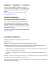
Hardware installation One optional video connector (1), one optional Front LAN connector (2) and two additional USB connectors (3) are located on the front of the server (figure 3): Figure 3: Front side connectors I If components with large power requirements (e.g. external USB hard disk drives) are connected simultaneously, these USB connectors may be switched off.
Hardware installation 5.4 Connecting the server to the mains In its basic configuration level the server has a hot-plug power supply unit. A second hot-plug power supply unit can be added to ensure a redundant power supply. If one power supply unit is defective, the other then guarantees unimpaired operation. Each hot-plug power supply unit can be replaced during operation (see the "PRIMERGY RX300 S7 Server Upgrade and Maintenance Manual").
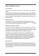
Hardware installation 5.4.1 Using the cable clamp You can secure the power cords in a cable clamp to ensure that the insulated connectors cannot be disconnected from the server accidentally. Figure 4: Cable clamp Ê Pull the cable clamp up (1). Ê Thread the power cord through the cable clamp (2). Ê Press the cable clamp down until it engages to secure the cable (3).
Hardware installation 5.5 Notes on connecting/disconnecting cables V CAUTION! Always read the documentation supplied with the device you wish to connect. Never connect, or disconnect cables during a thunderstorm. Never pull on a cable when disconnecting it. Always take hold of the cable by the plug. Follow the sequence described below to connect or disconnect external devices to or from the server: Be sure to wait for 10 seconds or more after shutdown before turning the server on.
Hardware installation Information for ensuring electromagnetic compatibility All data and signal cables must have sufficient shielding. The use of cable type S/FTP Cat5 or better is recommended. Use of unshielded or badly shielded cables may lead to increased emission of interference and/or reduced fault-tolerance of the device.
6 Starting up and operation V CAUTION! Please note the safety instructions in chapter "Important information" on page 35 6.1 Controls and indicators 6.1.
Starting up and operation 9 Temperature error indicator 13 PSU error indicator 10 Fan error indicator 14 CPU error indicator 11 Global Error indicator 15 HDD/SSD error indicator 12 Memory error indicator 16 ID card ID card You can pull out the ID card as far as it will go and push it back again. The ID card contains various system information, such as the product name, serial number, order number, MAC addresses and DNS name (in the Japanese market, only the product name and the serial number). 6.1.
Starting up and operation RST Reset button Pressing the reset button reboots the system. V CAUTION! Risk of loss of data! ID ID button Lights up (blue) on the front and on the rear of the server when the ID button is pressed. Both ID indicators are synchronized.
Starting up and operation 6.1.1.2 Indicators on the control panel Power-on indicator (two colors) Lights up green when the server is switched ON. Lights up orange when the server is switched OFF, but mains voltage is present (standby mode). HDD/SSD activity indicator (green) Lights up green when an internal drive (HDD or backup drive) is being accessed. ! Global Error indicator (orange) – Lights up orange if a prefailure event has been detected that requires (precautionary) service intervention.
Starting up and operation CSS CSS indicator (yellow) – Lights up yellow if a prefailure event was detected for a CSS component that you can fix yourself (for reasons of precaution) with the CSS concept. – Flashes yellow if an error was detected that you can fix yourself with the CSS concept. – Does not light up when the system is OK. If the event is still acute after a power cycle, the indicator is activated after the restart. The indicator also lights up in standby mode.
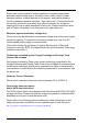
Starting up and operation 6.1.1.3 Indicators on the drives Optical drive activity indicator Lights up green when the storage medium is being accessed. Hard disk drive indicators 1 2 1 2 Figure 6: Indicators on the 3.5 inch and 2.
Starting up and operation Solid state disk indicators Figure 7: Indicators on the SSD modules 1 LED green BUSY – Lights up: SSD in active phase – Does not light: SSD inactive (drive inactive) 2 LED FAULT (orange) orange (in conjunction with a RAID controller) – Does not light: no error – Lights up: Faulty or Rebuild Stopped (drive defective/needs replacing, a rebuild process was stopped or the module is not correctly inserted) – Slow flashing: Rebuild (the data is being restored after changing a drive)
Starting up and operation 6.1.2 Rear of server CSS, Global Error and ID indicators Figure 8: Indicator on the connection panel: Global Error/CSS/ID indicator 1 Global Error/CSS/ID indicator (orange, yellow and blue) ! Global Error indicator (orange) – Lights up orange if a prefailure event has been detected that requires (precautionary) service intervention. – Flashes orange if an error was detected that requires service intervention. – Does not light up if there is no critical event.
Starting up and operation CSS CSS indicator (yellow) – Lights up yellow if a prefailure event was detected for a CSS component that you can fix yourself (for reasons of precaution) with the CSS concept. – Flashes yellow if an error was detected that you can fix yourself with the CSS concept. – Does not light up when the system is OK. If the event is still acute after a power cycle, the indicator is activated after the restart. The indicator also lights up in standby mode.
Starting up and operation LAN indicators Figure 9: Indicators on the connection panel: LAN indicators 1 LAN link/transfer Steady green signal when a LAN connection exists. LAN speed Steady yellow signal in the event of a LAN transfer rate of 1 Gbit/s Remains dark when no LAN connection exists. Flashes green when LAN transfer takes place. 2 Steady green signal in the event of a LAN transfer rate of 100 Mbit/s. Remains dark in the event of a LAN transfer rate of 10 Mbit/s.
Starting up and operation Indicators on the hot-plug power supply unit Figure 10: Indicator on hot-plug power supply unit 1 Indicator on hot-plug power supply unit (two colors) Flashes green when the server is switched off, but mains voltage is present (standby mode). Lights up green when the server is switched on and functioning properly. Lights up orange in case of OCP/OVP or when the fan of the power supply unit has failed.
Starting up and operation 6.1.3 Indicators of the hot-plug fans A status indicator (LED on the system board) is assigned to each fan. The status indicators are not visible unless the housing is open. The respective LED is set with commands in Server Management.
Starting up and operation 6.2 Switching the server on and off V CAUTION! ● If nothing appears on the screen but flickering stripes after switching on the server, switch the server off immediately (see chapter "Troubleshooting and tips" on page 81). ● The On/Off button does not disconnect the server from the mains voltage. To completely disconnect it from the mains voltage, remove the power plug(s) from all PSU inlet connectors. ● Do not move, strike, or shake the server when it is turned on.
Starting up and operation Ê Follow the on-screen instructions (see also section "Configuring the server and installing the operating system with the ServerView Installation Manager" on page 76 or section "Configuring the server and installing the operating system without the ServerView Installation Manager" on page 77). – System already installed: Ê Press the On/Off button. The server is switched on, performs a system test and boots the operating system.
Starting up and operation The server automatically reboots following a power failure (depending on the settings in the BIOS or in iRMC S3). – Power button override The system can be switched off (hard power off) by keeping the On/Off button (approximately 4 - 5 seconds). V CAUTION! There is a risk that data may be lost. – iRMC S3 iRMC S3 offers various options for switching the server on and off, e.g. via the Power On Off page of the iRMC S3 Web interface.
Starting up and operation 6.3 Configuring the server This section contains information about configuring the server and installing the operating system. I Make sure that the power saving functions are disabled in the Power menu of the BIOS Setup during operation. 6.3.1 Configuring the onboard SAS/SATA controller A SAS/SATA controller is integrated on the system board. You can configure the onboard controller either before or during installation with the ServerView Installation Manager.
Starting up and operation 6.3.2 Configuring the SAS/SATA RAID controller The server has a SAS/SATA RAID controller with "MegaRAID functionality". You can configure the SAS/SATA RAID controller either before or during installation with the ServerView Installation Manager. Using the ServerView Installation Manager is recommended. I A separate utility is available to the controller for MegaRAID configuration.
Starting up and operation 6.3.3 Configuring the server and installing the operating system with the ServerView Installation Manager Using the ServerView Installation Manager on the ServerView Suite DVD 1 provided, you can conveniently configure the server and install the operating system. This includes configuring the server-specific settings using the ServerView Configuration Manager and configuring the RAID controller using the ServerView RAID Manager.
Starting up and operation 6.3.4 Configuring the server and installing the operating system without the ServerView Installation Manager Configuring SAS/SATA RAID controller with "Integrated Mirroring Enhanced" Configure the controller as described in section "Configuring the SAS/SATA RAID controller" on page 75. Configuring SAS/SATA RAID controller with "MegaRAID functionality" Configure the controller as described in section "Configuring the SAS/SATA RAID controller" on page 75.
Starting up and operation 6.4 Cleaning the server V CAUTION! Switch off the server and disconnect the power plugs from the properly grounded power outlets. Do not clean any interior parts yourself; leave this job to a service technician. Do not use any cleaning agents that contain abrasives or may corrode plastic. Ensure that no liquid enters the system. Ensure that the ventilation areas of the server and the monitor are clear. Do not use any cleaning sprays (including flammable types).
7 Property and data protection The rack model is protected against unauthorized access by a lockable rack door. To protect your system and data internally against unauthorized access, you can use the BIOS Setup security functions. 7.1 BIOS Setup security functions The Security menu in BIOS Setup offers various options for protecting your data from unauthorized access. By combining these options, you can also achieve optimum protection for your system.
Property and data protection 80 Operating Manual RX300 S7
8 Troubleshooting and tips V CAUTION! Follow the safety instructions in the "Safety notes and regulations" manual or " 安全上のご注意 " and in chapter "Important information" on page 35. If a fault occurs, attempt to resolve it using the measures described: – in this chapter, – in the documentation for the connected devices, – in the help systems of the software used. If you fail to correct the problem, proceed as follows: Ê Make a list of the steps performed and the circumstances that led to the fault.
Troubleshooting and tips 8.2 Server switches itself off Server Management has detected an error Ê Check the error list of System Event Log in ServerView Operations Manager or in the iRMC S3 web interface, and attempt to eliminate the error. 8.3 Screen remains blank Monitor is switched off Ê Switch on your monitor. Screen has gone blank Ê Press any key on the keyboard. or Ê Deactivate screen saver. Enter the appropriate password.
Troubleshooting and tips 8.4 Flickering stripes on monitor screen V CAUTION! Switch off the server immediately. Risk of damaging the server. Monitor does not support the set horizontal frequency Ê Find out which horizontal frequency your monitor screen supports. You will find the horizontal frequency (also known as line frequency or horizontal deflection frequency) in the documentation for your monitor.
Troubleshooting and tips 8.6 Incorrect date and time Ê Set the date and time in the operating system or in the BIOS Setup under the Main menu, using System Date and System Time respectively. I Note that the operating system may affect the system time. For example, the operating system time may deviate from the system time under Linux, and would overwrite the system time in the default setting on shutdown.
Troubleshooting and tips 8.9 Added drive reported as defective RAID controller is not configured for this drive The drive was probably installed when the system was switched off. Ê Reconfigure the RAID controller for the drive using the corresponding utility. Information is provided in the documentation for the RAID controller. or Ê Remove and reinstall the drive while the system is switched ON. If the drive continues to be shown as defective, then replace it. 8.
Troubleshooting and tips Ê Although continued use within the temperature boundaries poses no problems within itself, reconsider the surrounding environment conditions if this log is output or if ServerView issues this notification. 8.13 No effect of keyboard or mouse Typing the keyboard does not display any characters, or the mouse cursor does not move. Ê Check to see whether the keyboard and mouse are connected properly.