
Datasheet


Thermal Specifications and Design Considerations
80
Quad-Core Intel® Xeon® Processor 3200 Series Datasheet
5.3 Platform Environment Control Interface (PECI)
5.3.1 Introduction
Platform Environment Control Interface (PECI) offers an interface for thermal
monitoring of Intel processor and chipset components. It uses a single wire; thus,
alleviating routing congestion issues. PECI uses CRC checking on the host side to
ensure reliable transfers between the host and client devices. Also, data transfer
speeds across the PECI interface are negotiable within a wide range (2 Kbps to
2 Mbps). The PECI interface on the processor is disabled by default and must be
enabled through BIOS.
5.3.1.1 Key Difference with Legacy Diode-Based Thermal Management
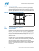
Fan speed control solutions based on PECI use a T
CONTROL
value stored in the processor
IA32_TEMPERATURE_TARGET MSR. The T
CONTROL
MSR uses the same offset
temperature format as PECI though it contains no sign bit. Thermal management
devices should infer the T
CONTROL
value as negative. Thermal management algorithms
should use the relative temperature value delivered over PECI in conjunction with the
T
CONTROL
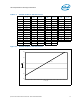
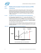
MSR value to control or optimize fan speeds. Figure 5-4 shows a conceptual
fan control diagram using PECI temperatures.
The relative temperature value reported over PECI represents the delta below the onset
of thermal control circuit (TCC) activation as indicated by PROCHOT# assertions. As the
temperature approaches TCC activation, the PECI value approaches zero. TCC activates
at a PECI count of zero.
.
Figure 5-4. Conceptual Fan Control on PECI-Based Platforms
Min
Max
Fan Speed
(RPM)
T
CONTROL
Setting
TCC Activation
Temperature
PECI = 0
PECI = -10
PECI = -20
Temperature
Note: Not intended to depict actual implementation