ServerView Resource Orchestrator Cloud Edition V3.1.
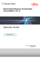
Preface Resource Orchestrator Documentation Road Map The documentation road map for Resource Orchestrator is as shown below. Resource Orchestrator Documentation Road Map Point Refer to the user role manuals displayed in the table below for roles that are not in the diagram.
Purpose This manual explains how to operate ServerView Resource Orchestrator (hereinafter Resource Orchestrator). Target Readers This manual is written for system administrators who will use Resource Orchestrator to operate the infrastructure in private cloud or data center environments. When setting up systems, it is assumed that readers have the basic knowledge required to configure the servers, storage, network devices, and server virtualization software to be installed.
Chapter 12 Collecting Power Consumption Data and Displaying Graphs Explains how to export the power consumption data collected from registered power monitoring targets and how to display it as graphs, and also describes the exported data's format. Chapter 13 Monitoring Resource Pools (Dashboard) Explains the monitoring of resource pools. Chapter 14 Monitoring L-Platforms Explains the monitoring of L-Platforms. Chapter 15 Accounting Explains charging.
[Physical Servers] Sections related to physical servers [VM host] Sections related to Windows Server 2008 with VMware or Hyper-V enabled - Unless specified otherwise, the blade servers mentioned in this manual refer to PRIMERGY BX servers. - Oracle Solaris may also be indicated as Solaris, Solaris Operating System, or Solaris OS. - References and character strings or values requiring emphasis are indicated using double quotes ( " ).
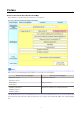
Abbreviation Products Windows Vista(R) Ultimate Microsoft(R) Windows(R) XP Professional operating system Windows Server 2008 Microsoft(R) Windows Server(R) 2008 Standard Microsoft(R) Windows Server(R) 2008 Enterprise Microsoft(R) Windows Server(R) 2008 R2 Standard Microsoft(R) Windows Server(R) 2008 R2 Enterprise Microsoft(R) Windows Server(R) 2008 R2 Datacenter Windows 2008 x86 Edition Microsoft(R) Windows Server(R) 2008 Standard (x86) Microsoft(R) Windows Server(R) 2008 Enterprise (x86) Windows 2008
Abbreviation Products Red Hat(R) Enterprise Linux(R) 5.3 (for Intel64) Red Hat(R) Enterprise Linux(R) 5.4 (for x86) Red Hat(R) Enterprise Linux(R) 5.4 (for Intel64) Red Hat(R) Enterprise Linux(R) 5.5 (for x86) Red Hat(R) Enterprise Linux(R) 5.5 (for Intel64) Red Hat(R) Enterprise Linux(R) 5.6 (for x86) Red Hat(R) Enterprise Linux(R) 5.6 (for Intel64) Red Hat(R) Enterprise Linux(R) 5.7 (for x86) Red Hat(R) Enterprise Linux(R) 5.7 (for Intel64) Red Hat(R) Enterprise Linux(R) 5.
Abbreviation Products VMware VMware vSphere(R) 4 VMware vSphere(R) 4.1 VMware vSphere(R) 5 VMware ESX VMware(R) ESX(R) VMware ESX 4 VMware(R) ESX(R) 4 VMware ESXi VMware(R) ESXi(TM) VMware ESXi 5.0 VMware(R) ESXi(TM) 5.0 VMware Tools VMware(R) Tools VMware vSphere 4.0 VMware vSphere(R) 4.0 VMware vSphere 4.1 VMware vSphere(R) 4.
- Linux is a trademark or registered trademark of Linus Torvalds in the United States and other countries. - Microsoft, Windows, MS, MS-DOS, Windows XP, Windows Server, Windows Vista, Windows 7, Excel, Active Directory, and Internet Explorer are either registered trademarks or trademarks of Microsoft Corporation in the United States and other countries. - NetApp is a registered trademark of Network Appliance, Inc. in the US and other countries.
Contents Part 1 Overview........................................................................................................................................................................1 Chapter 1 Overview of Operations, Maintenance, and Monitoring...........................................................................................2 1.1 Operation, Maintenance, and Monitoring by Infrastructure Administrators.......................................................................................
8.5.5.2 How to Modify Application Process to be Used.................................................................................................................29 8.5.6 Editing the Environment Setup File for the L-Platform API......................................................................................................29 8.5.7 Edit the License Agreement................................................................................................................................................
10.1.4.3 Starting the Manager..........................................................................................................................................................88 10.1.4.4 Disabling L-Platform Applications....................................................................................................................................88 10.1.4.5 Updating the configuration information in the operational status information................................................................
Chapter 16 Monitoring Logs.................................................................................................................................................135 16.1 Operation Logs..............................................................................................................................................................................135 16.1.1 Overview.............................................................................................................................
Part 1 Overview Chapter 1 Overview of Operations, Maintenance, and Monitoring...................................................................
Chapter 1 Overview of Operations, Maintenance, and Monitoring This chapter provides an overview of operation, maintenance, and monitoring of Resource Orchestrator. For additional information on the operation, maintenance, and monitoring of this product, refer to the configuration information in the "Setup Guide CE". Flow of Service Provision Using Applications The flow of service provision using applications in an environment where Resource Orchestrator has been installed is as shown below. Figure 1.
5. Configure firewalls When configuring an application on an L-Server that has been deployed on the public LAN, the tenant user needs to create a rule that enables access to that L-Server from the public LAN. 6. Configure applications The tenant user performs the installation and environment settings necessary for the application to be provided as a service by the L-Server. 7.
- Create a tenant administrator - Creation, modification, and deletion of user accounts - Management of templates - Creation, modification, and deletion of L-Platform templates (*) - Creation, modification, and deletion of L-Server templates * Note: To check subscription requests submitted by using a created L-Platform template, use a dual-role administrator account.
Part 2 Operation Chapter 2 Starting and Stopping Managers and Agents..................................................................................6 Chapter 3 Managing User Accounts...............................................................................................................11 Chapter 4 Managing Tenants.........................................................................................................................12 Chapter 5 Managing Templates....................................
Chapter 2 Starting and Stopping Managers and Agents This chapter explains how to manually start or stop managers and agents. To use Resource Orchestrator, both the manager and agents must be running. The manager and agent services are configured to start automatically upon startup of their respective servers (admin server, managed server). Normally, there should be no need to manually start or stop either the manager or agents. To start or stop a manager or an agent intentionally, refer to "2.
PXE Services DHCP Server (*) Systemwalker SQC DCM Interstage BPM Analytics eRule Engine (EFServer) Systemwalker MpJobsch9 Systemwalker MpMjes Systemwalker MpMjes9 Systemwalker Runbook Automation DB Service Shunsaku Conductor cmdbc Shunsaku Sorter cmdbo01 * Note: Required when managed servers belonging to different subnets from the admin server exist. From the Windows Control Panel, open [Administrative Tools]. Then, open the [Services] window to check the state of each service.
For details on the command, refer to "5.19 rcxmgrctl" in the "Reference Guide (Command/XML) CE". To start or stop a manager in a clustered configuration, use the cluster administration view (Cluster Admin). For details, refer to the PRIMECLUSTER manual. Note - When using ServerView Deployment Manager on an admin LAN, all services related to Resource Orchestrator will be automatically disabled. To prevent conflicts with ServerView Deployment Manager, do not start these services in order.
- Agent Service Resource Coordinator Agent - Related Services - Deployment Agent - Systemwalker SQC DCM From the Windows Control Panel, open [Administrative Tools]. Then, open the [Services] window to check the state of each service. The following explains how to start and stop each service. - Agent Service Agents can be started and stopped using the start and stop subcommands of the rcxadm agtctl command. For details of the command, refer to "5.3 rcxadm agtctl" in the "Reference Guide (Command/XML) CE".
# /etc/init.d/scwagent start # /etc/rc2.d/S99ssqcdcm start Stop # /etc/init.d/scwagent stop # /etc/rc0.d/K00ssqcdcm stop [Solaris] The agent consists of the following services. - Agent Service Execute the following commands to determine whether the agent is running or not. If those commands show that the processes for the agent and deployment services are running, then the agent can be asserted to be running.
Chapter 3 Managing User Accounts This chapter explains the management of user accounts. Creation, Viewing, and Modification of User Accounts Only users that hold the role of infrastructure administrator, tenant administrator, or administrator can create user accounts. For details on operations by infrastructure administrators, refer to "Chapter 3 Configuring Users for Infrastructure Administrators" in the "User's Guide for Infrastructure Administrators (Resource Management) CE".
Chapter 4 Managing Tenants This chapter explains the management of tenants. Tenant Creation The flow of tenant creation is as follows: 1. Register Tenants Input the tenant information and register tenants. 2. Create a Tenant Administrator Create a tenant administrator. 3. Create a Local Pool for Tenants The following two types of resource pool operations can be performed: - Local Pool A resource pool which can be used only for tenants.
Chapter 5 Managing Templates This chapter explains the management of templates. - L-Platform Templates An L-Platform template is the template to define the logical configuration of ICT resources and software. An L-Platform is composed of an L-Platform template. Use the [Template] tab to create, modify, and delete L-Platform templates. For details on the [Template] tab, refer to "Chapter 8 Template" in the "User's Guide for Infrastructure Administrators CE".
Chapter 6 Managing Resources and Resource Pools This chapter explains the management of resources and resource pools. 6.1 Managing Resource Pools This section explains the management of resource pools.
Chapter 7 Management of L-Platform This chapter explains how to management of L-Platform. 7.1 Review for L-Platform Usage Applications Use the [Request] tab of the ROR console to review applications to use from tenant users for operations such as usage application, configuration modification, and cancel of L-Platforms. For details on the [Request] tab, refer to "Chapter 10 Request" in the "User's Guide for Infrastructure Administrators CE". 7.
c. Importing the L-Server for which network information has been set Refer to "7.2.3.2 Importing L-Servers". - Import L-Servers created in the ROR console into the L-Platform Refer to "7.2.3.2 Importing L-Servers". 7.2.3.1 Network Information Settings for Converted L-Servers Set the network information for the L-Servers converted in "Use of Physical Servers or Virtual Machines as L-Servers". Execute the rcxadm lserver attach -define command to set network information.
The infrastructure administrator must look up the IP addresses and the host name in the L-Platform management window and the default gateway in the resource management window, and then connect a console to the deployed server and configure the OS manually. Users cannot access the server until this configuration is completed.
- Configuration or modification of network devices such as firewalls or server load balancers Figure 7.1 Flow of Corrective Actions when a Problem Occurs during L-Platform Operation 1. The tenant user performs L-Platform creation, modification or deletion, or network device configuration or modification. 2. Problem Occurrence L-Platform creation, modification or deletion, or network device configuration or modification ends abnormally. 3.
For information on creating L-Server templates, refer to "Chapter 15 L-Server Template Operations" in the "User's Guide for Infrastructure Administrators (Resource Management) CE". If the settings are changed after deployment, change the "Type of Server(specifications)" by reconfiguring the L-Platform. Register different L-Server templates where heartbeat settings are enabled and disabled. Also use L-Server template names that make it easy to distinguish whether heartbeat settings are enabled or disabled.
- L-Server template name where automatic server release settings are enabled VMware_Small_Repurpose 7.2.10 Definition VM Specific Information Definition File If an overcommit value has not been set for the L-Server template selected in "type" on the Reconfiguration page of the L-Platform subscription window, then the values set in VM specific information definition file will not be used, even if the file is used. Rather, the following values are applied: [VMware] - CPU Reserved: 0.
Chapter 8 Changing Settings This chapter explains how to change settings. 8.1 Registering and Deleting Application Process Assessors This section explains how to register and delete application process assessors. 8.1.1 Registering an Application Process Assessor This section explains how to register an infrastructure administrator or dual-role administrator as an application process assessor.
# Delete manager from IflowUsers dn: cn=IflowUsers,ou=group,dc=fujitsu,dc=com changetype: modify delete: member member:cn=manager,ou=users,dc=fujitsu,dc=com 2. Execute the ldapmodify command. [Windows Manager] Specify the created LDIF file, and then execute the ldapmodify command. OpenDS Installation_folder\bat\ldapmodify.bat" -p -f -D -w An execution example is shown below.
Settings for the Email Sent from Tenant Management Email sent from the tenant management will be enabled only if the tenant has set the Performing tenant management setting. When an operation such as registering a tenant or adding or changing a user has been performed, notification to that effect is sent to the tenant administrators, tenant users, and tenant email addresses within that same tenant. Refer to "19.
1. Modify the portal.properties file. Open the following file: [Windows Manager] Installation_folder\RCXCTMG\SecurityManagement\conf\portal.properties [Linux Manager] /etc/opt/FJSVctsec/conf/portal.properties Change the port numbers specified in the following URLs. Set the same values in the port numbers: - portalSsl.url - authedPortal.url - sendmail.auth.url 2. Start the Interstage Management Console.
2. Modify the managerview_config.xml file. Open the following file. [Windows Manager] Installation_folder\RCXCTMG\MyPortal\config\managerview_config.xml [Linux Manager] /etc/opt/FJSVctmyp/config/managerview_config.xml Modify the value of the entry tag with vsys-port as the key value. - The entry tag with vsys-port as the key value An example is shown below. The section in italics is the information to be modified. 8013 8.
- Enter a string of up to 30 characters for the schedule. Commas (,) cannot be included. - Enter a string of up to 250 characters for the message. Commas (,) can be included. Example of settings 2011/11/11,Maintenance is scheduled for the Kanto network on the weekend. ,Upgraded the operation management software. 8.5 Settings for L-Platform Management This section explains how to change the settings for L-Platform management. 8.5.
8.5.2 Subnet Settings at Segment Editing It is possible to change the method for setting up the subnets that are allocated to segments when performing an application to use LPlatform. Use the following procedure to use network resource names rather than IP addresses to select which subnets to allocate to segments during subnet setup. Refer to "8.3.14 L-Platform Reconfiguration" in the "User's Guide for Tenant Administrators" for details on changing the configuration.
[Linux Manager] /etc/opt/FJSVctmyp/config/managerview_config.xml 2. Add the following key and value: Key name enable-easy-reconfigure Content false: Disables the function. (This is the default value. This is applicable even when this key is not defined.) true : Enables the function 3. Save the file. 4. Restart the manager. Refer to "2.1 Starting and Stopping the Manager" for information on how to restart the manager. 8.5.
4. Restart the manager. Refer to "2.1 Starting and Stopping the Manager" for information on how to restart the manager. 8.5.5 Application Process Settings This section explains how to modify the application process settings. 8.5.5.1 How to Modify the Application Process Settings This section explains how to modify the setting whether to use the application process.
8.5.10 Settings for the Maximum Number of Connections for the L-Platform Template The maximum number of L-Servers that can be placed in an L-Platform Template and the maximum number of NICs in a segment of an L-Platform Template can be modified. 1. Use the editor to open the settings file. The settings file is stored in the following location: [Windows Manager] Installation_folder\RCXCTMG\MyPortal\config\managerview_config.xml [Linux Manager] /etc/opt/FJSVctmyp/config/managerview_config.xml 2.
8.6.1 Settings for Tenant Management and Account Management This section explains how to change the settings for the tenant management and the account management. - Display setting for user list This section explains the procedure for changing the setting for whether or not tenant users are to be displayed, when an infrastructure administrators has used the tenant management to display the user list.
/etc/opt/FJSVctsec/conf/portal.properties 2. The following information must be modified: Setting item Settings visible.tenantuser Setting for infrastructure administrators operation Specify "on" if both tenant administrators and tenant users are to be displayed in the user list for the tenant management, and specify "off" if only tenant administrators are to be displayed. The initial value is "on".
Setting item Settings user password button will not be displayed in the Account window of the account management. leftMenu.modifyUser.user.visible Setting for tenant user operation leftMenu.changePassword.user.visible Specify "on" if changing user account is to be performed using the account management, and specify "off" if it is not to be performed. The initial value is "on".
Setting item Settings If "false" has been specified, the Set password button will not be displayed in the User List window of the tenant management. In addition, the Change user password button will not be displayed in the Account window of the account management. Note that, if "false" is specified, users must already be registered in the directory service. Perform user registration according to the directory service to be used. * note : this can be set by "Setup Wizard" on the ROR Console.
/etc/opt/FJSVcfmg/config/vsys_config.xml 2. The following information must be modified: Key use-charge (*) Description Specifies whether usage fee (the estimated price) for the L-Platform template will be displayed. Default value no - yes: Display - no: Do not display * note: this can be set by "Setup Wizard" on the ROR Console. A setting example is shown below. ...
software is used, the usage fee (the estimated price) will be calculated using the operating value regardless of whether or not overcommit is enabled or disabled. A setting example is shown below. 3 true ... omitted 5. Restart the manager. Refer to "2.1 Starting and Stopping the Manager" for information on how to restart the manager. 8.7.
2. Change the relevant items in the operational settings file for metering logs: Key retention_period Description Retention period of log entries Logs will be deleted once their retention period has passed. Default value 0000-03-00 Use the following format to specify the retention period: YYYY-MM-DD Example: 0000-03-00: Retain logs for 3 months. 0005-00-00: Retain logs for 5 years.
Key Description Default value A number of days cannot be specified with this method. *1: Changes to this setting are enabled by executing the Change periodic log schedule settings command after changing the settings file. *2: If periodic_log_schedule_type is DAILY, the periodic_log_schedule_day value will be ignored. An example of setting the operational settings file is shown below: # delete setting of meteringlog database # YYYY-MM-DD # ex.
Key accounting.use (*) Description Default value Specify whether to use the usage charge calculator. no - yes: Use the usage charge calculator. - no: Do not use the usage charge calculator. gui.cutoffdate (*) Specify the default for the cut-off date displayed in the tenant management window of the ROR console. Specify a value between 1 and 31. In cases where the specified date does not exist, the cut-off date will be the end of the month.
If the L-Platform Management overcommit function is enabled, the CPU and memory settings displayed in the System Condition Server List can be changed. Refer to "19.6 Settings for the Overcommit Function" in the "Setup Guide CE" for information on the L-Platform Management overcommit function settings. Note If the overcommit function is used, the settings must match those of the L-Platform Management overcommit function.
- When editing the viewlist_en.xml file, do not change any settings items other than serverByOrg_ROR.bottom.column.11.isEnable and serverByOrg_ROR.bottom.column.14.isEnable. - Save the viewlist_en.xml file before you edit the file. If any settings other than serverByOrg_ROR.bottom.column.11.isEnable and serverByOrg_ROR.bottom.column.14.isEnable are changed, restore the saved file. 8.
Part 3 Retention Chapter 9 Hardware Maintenance..................................................................................................................43 Chapter 10 Backup and Restoration..............................................................................................................
Chapter 9 Hardware Maintenance This chapter explains how to perform hardware maintenance. 9.1 Overview This section explains how to perform maintenance on the hardware devices managed by Resource Orchestrator. Hardware Maintenance Flow The flow of maintenance for hardware used to operate an L-Platform is shown below. Figure 9.1 Flow of Maintenance for L-Platform Hardware 1.
- When using a server for which spare servers are not configured When using a server for which spare servers are not configured, the infrastructure administrator places the managed server into maintenance mode. For details on maintenance mode, refer to "Appendix C Maintenance Mode" in the "User's Guide for Infrastructure Administrators (Resource Management) CE".
Flow of Corrective Actions when Hardware Fails The flow of corrective actions when hardware fails is as below. Figure 9.2 Flow of Corrective Actions when Hardware on which an L-Platform Operates Fails 1.
Figure 9.3 Flow of Hardware Maintenance when a Server Fails *1: For details on how to identify failures, refer to "11.3 Addressing Resource Failures". *2: For details on how to configure and release the maintenance mode, refer to "Appendix C Maintenance Mode" in the "User's Guide for Infrastructure Administrators (Resource Management) CE". *3: For details on server switchover, failback, and takeover, refer to "Chapter 4 Server Switchover" in the "Operation Guide VE".
- Replacing Non-Server Hardware Replace registered chassis, management blades, or any other hardware components external to servers. For details on replacing non-server hardware, refer to "9.3.4 Replacing Non-server Hardware". 9.2 Blade Server Maintenance This section explains the maintenance of blade servers. 9.2.1 Maintenance LED This section explains how to operate maintenance LEDs. Activating a server blade's maintenance LED make it easy to identify a server from others.
2. Click . The maintenance LED is turned off. 9.2.2 Reconfiguration of Hardware Properties This section explains how to re-configure hardware properties for replaced hardware. After hardware replacement, it is necessary to re-configure Resource Orchestrator with the new hardware properties. For PRIMERGY BX servers, the hardware properties are automatically re-configured.
1. After hardware replacement, insert the server and check that the following message is displayed in the event log. Server blade added After the message is displayed, shut down the server if it is still powered on. 2. After approximately 30 seconds, right-click the target server in the ROR console server resource tree, and select [Hardware Maintenance]-[Re-configure] from the popup menu. The [Re-configure Hardware Properties] dialog is displayed. 3. Click .
- Replacing a Server with no Spare Server Assigned Use the following procedure to smoothly replace a server and resume its applications. 1. Place the Server into Maintenance Mode Place the primary server to replace into maintenance mode. For details on maintenance mode, refer to "Appendix C Maintenance Mode" in the "User's Guide for Infrastructure Administrators (Resource Management) CE". 2. Create a System Image Backup For local boot servers, create a system image backup when possible.
For details on BIOS settings, refer to "8.2 Configure the Server Environment" in the "Design Guide CE". Shut down the server after completing BIOS settings. 3. Re-configure Hardware Properties after Replacement After replacing the server, re-configure Resource Orchestrator with the latest hardware properties. For details on how to re-configure hardware properties, refer to "9.3.1 Reconfiguration of Hardware Properties".
- Replacing Storage Blades No specific action is required in Resource Orchestrator when replacing a storage blade that does not contain the boot disk of a server blade. Use the following procedure to replace a storage blade that contains the boot disk of a server blade. 1. Replace the storage blade. 2. Insert the server blade's boot disk in the new storage blade. 3. If the boot disk's content was backed up, restore it.
Re-configuring Hardware Properties after Server Replacement - For Rack Mount and Tower Servers Use the following procedure to re-configure properties for replaced hardware. 1. If the agent or ServerView Agents has already been registered, power on the server. Additional Information When a server using SAN boot has a hardware exchange that results in the MAC address used for the admin LAN being changed, the OS and an agent cannot be started.
- Restart the related services described in "2.2 Starting and Stopping an Agent" 9.3.2 Replacing Servers This section details the procedure to follow when replacing servers. Information - Follow the same procedure when replacing servers where VM hosts are running. - No specific action is required in Resource Orchestrator when replacing admin servers or HBA address rename setup service servers.
4. Replace the Server Replace the server. Change the BIOS settings of the replacement server to match the operating environment. For details on BIOS settings, refer to "8.2 Configure the Server Environment" in the "Design Guide CE". Shut down the server after completing BIOS settings. Configure the remote management controller of the replacement server with the same IP address, user name, password, and SNMP trap destination as those set on the original server. 5.
- When Replacing an HBA 1. Perform Server Switchover Switch over the server to replace with its spare server. For server switchover, refer to "Chapter 4 Server Switchover" in the "Operation Guide VE". The server to replace is automatically powered off after switchover. 2. Replace the Server Replace the HBA of the server. Change the OBP settings of the replacement server to match the operating environment. For details on OBP settings, refer to "8.2 Configure the Server Environment" in the "Design Guide CE".
For details on OBP settings, refer to "8.2 Configure the Server Environment" in the "Design Guide CE". Shut down the server after completing OBP settings. When the target CA was deleted in step 1., configure zoning and host affinity settings in the WWPN value of the replacement HBA. For details, refer to the ESC users guide. 3. Change the WWN Information Settings Change the WWN information settings for after server replacement to the WWN value of the HBA after server replacement.
3. Power OFF Shut down the server to replace if it is still powered on. For details on shutting down servers, refer to "Chapter 14 Power Control" in the "User's Guide VE". 4. Replace the Server Replace the server. Use the Maintenance Wizard of the Management Board Web-UI to perform replacement. For details on the Maintenance Wizard, refer to the PRIMEQUEST manual. Also, change the BIOS settings of the replacement server to match the operating environment. For details on BIOS settings, refer to "8.
- Replacing and Adding Network Interfaces (Admin LAN, Public LAN) The procedure used to replace and add network interfaces is the same as that described in "9.3.2 Replacing Servers". For details, refer to "9.3.2 Replacing Servers". When adding or removing network interfaces, if the target server is running Red Hat Enterprise Linux 5 or Citrix XenServer, after completing the steps described in "9.3.
Information The backup and restore functions available in Resource Orchestrator can be used to restore the boot disk contents. For details, refer to "Chapter 16 Backup and Restore" in the "User's Guide VE". - Replacing a System Board The procedure used to replace a system board is the same as that described in "9.3.2 Replacing Servers". - Replacing an IO Board No specific action is required in Resource Orchestrator when replacing an IO board.
9.5 Network Device Maintenance This section explains how to maintain network devices that are the target of management in Resource Orchestrator. 9.5.1 Replacement Procedure of Network Devices This section explains the procedure to replace network devices when it becomes necessary due to failure. Figure 9.
2. Change the target network device to the "maintenance mode". 3. Replace the network devices. (Hardware maintenance person) 4. Restore configuration of replaced network device along by maintenance procedure of network device. 5. Release the "maintenance mode" of network devices, when problems with network devices after replacement have been solved. 6. Notification that maintenance operations are complete. When the Management Function for Network Device Configuration Files is Used 1.
When the management function for network device configuration files is not used 1. Announcement of planned maintenance operations. 2. Log in the network device directly to check if the target network device of replacement is in active status or standby status. When the target network device of replacement is in active status, switch over the device with the standby network device of redundancy configuration, and change the status of target network device for replacement from active status to standby status.
2. Restore network device file. Information - When replaced network device is "Cisco ASA 5500 series", operating restoration by rcxadm netdevice cfrestore command is not required. By function of "Cisco ASA 5500 series", same configuration as device of active state is reflected automatically. For detail, please refer to manual of "Cisco ASA 5500 series". - For restoration of network device file, please refer to "10.2.3 Restoration of Network Devices".
2. Set the status of the network device before replacement to standby, and replace the device When replacing multiple network devices of redundancy configurations simultaneously, perform replacement operations in units of the same redundancy configurations. - When the network device to replace has failed, step 4. cannot be performed. It is recommended to back up environments regularly in preparation for failures of network devices.
8. Release the network device from "maintenance mode", after checking that problems with network devices with standby status have been solved. 9. Switch over the network device in active status that is the target of regular maintenance and the network device of the redundancy configuration which is in standby status. 10. Then change the status of the remaining network device that is the target of regular maintenance from operational status to standby status, and perform steps 3. to 8. 11.
Figure 9.5 Image of L2 Switches to Add 1. Design additional configurations. (Network device administrator) 2. Provide the additional network device information to the infrastructure administrator. (Network device administrator) Add a network device in the state where the following operations have been completed. - Initial configuration - Operation test - Integration of the device into a physical network configuration 3. Register the resources of the server.
6. When the following applies to the additional network device, create and register rulesets. - When adding an L2 switch of a model for which sample scripts are not prepared, or an L2 switch of a model that has not been used in the system until now. In this case, it is necessary to create a directory to allocate rulesets to.
Figure 9.6 Image of Tenants to Add 1. Design additional configurations. (Network device administrator) 2. Provide the additional network device information to the infrastructure administrator. (Network device administrator) Add a network device in the state where the following operations have been completed. - Initial configuration - Operation test - Integration of the device into a physical network configuration 3. Register the resources of the server.
5. Register the added firewall, server load balancer, and L2 switch as network devices. Use the rcxadm netdevice create command to register as a network device. 6. When the following applies to the additional network device, create and register rulesets.
2. Create network configuration information (XML definition) using the acquired network device information. 3. Confirm there are no differences besides the link information (under Links tag) regarding the added or modified destinations for connection, by comparing the network configuration information of network devices registered in Resource Orchestrator and the network configuration information created in 2.
3. Re-configure the power monitoring device's hardware properties. a. In the ROR console server resource tree, right-click the target power monitoring device (PDU or UPS), and from the popup menu, select [Hardware Maintenance]-[Re-configure]. The [Re-configure Hardware Properties] dialog is displayed. b. Click . The target power monitoring device's hardware properties are re-configured.
Chapter 10 Backup and Restoration This chapter describes how to operate the backup and restoration of ServerView Resource Orchestrator Cloud Edition. 10.1 Backup and Restoration of Admin Servers This section describes how to operate the backup and restoration of the admin server of ServerView Resource Orchestrator Cloud Edition. Backing up the Admin Server The two methods of backing up the Management Server are shown below.
Usually, for each 16 MB written, the WAL file being written to is switched, and the WAL file for which writing has been completed is saved to the "wal" directory under the backup directory. Periodically executing the rcxmgrbackup command allows the contents of updates to the database that are recorded in saved WAL files to be maintained for a certain period of time.
- Do not delete backup resources during execution of the restore command. - To delete backup resources, delete the folder specified in the backup destination as well as all folders and files under that folder. - Backup to the following media cannot be performed using the backup command: - Backup to optical disks such as CD-R and DVD-R To back up user resources to optical disks, back up once to local disks, and then write to the media. - Backup to folders that include spaces.
Target Resources When Backup is Necessary Necessity of Stopping Managers Remarks Note) If the following definition files are to be backed up, the Manager must be stopped and offline backup must be performed.
Target Resources Disk Space Necessary for the Backup compressing it. Please prepare the backup area referring to this size. Every time, when backing up, it is necessary. Therefore, when the backup is executed three times for instance, the capacity of image save area is three times necessary. For the capacity of the image storage area, refer to "2.4.2.5 Dynamic Disk Space" in the "Design Guide VE".
Target Resources Disk Space Necessary for the Backup - /var/spool/mjes * Note: The backup of metering information is gathered under the control of the directory specified by the rcxmgrbackup command at an off-line backup, and it is gathered in the area besides the specified directory at an online backup. Please calculate a necessary amount of disk by backing up metering information referring to the following examples.
16 MB * 24 * 30 = 11.3 GB Table 10.7 Disk Space Necessary for Operation of Online Backup Disk space necessary for operation of online backup = Disk space necessary for base backup + Disk space necessary for difference backup = 1.3 GB + 11.3 GB = 12.6 GB Storage Destination for Backing Up Resources This section describes the storage destination for backing up Admin Server resources. Use the rcxmgrbackup command to specify a storage destination folder, except in the case of metering information.
- Memory Size : 16 GB - Command processing time - offline backup : 3 minutes - online backup (base backup) : 2 minutes - online backup (differential backup) : 2 minutes - restore : 4 minutes System Restart Point after Restoration In the system operations flow used by this product, the restart point of the system will vary according to the timing of the backup of resources.
10.1.2.1 Stopping the Manager Stop the Manager and check that it is in a stopped state. Stopping the Manager Execute the command shown below to stop the Manager. For details on the command, refer to "5.19 rcxmgrctl" in the "Reference Guide (Command/XML) CE".
Saving Image Management Information Check the following image management information, the number of stored snapshot generations and the image file storage folder: - Number of Stored Snapshot Generations - Image File Storage Folder Execute the following command to set the number of stored snapshot generations and the image storage folder information to a standard output, by redirecting the information to a file, and then saving it.
Note The backup command may not end normally at times, so do not perform the following operations: - Forced end using Ctrl+C during execution of the backup command - Stopping the Manager during execution of the backup command If the operations listed above have been performed, the following action will be required, depending on the status: Execute the command shown below the next time and any subsequent times the base backup does not end normally.
Execute the rcxmgrbackup command. Periodically executing the rcxmgrbackup command allows the contents of updates to the database that are recorded in saved WAL files to be maintained for a certain period of time. For example, when the rcxmgrbackup command is executed every hour, the contents of updates performed in the most recent one-hour period will be saved. For details on the command, refer to "6.6 rcxmgrbackup" in the "Reference Guide (Command/XML) CE".
2. To manage tasks hierarchically, use the following procedure to create a folder: a. In the Task Scheduler menu, after selecting Task Scheduler Library, select [Actions]-[New Folder], and then enter any folder name in the dialog box that is displayed and click . b. Selecting the created folder and then creating another folder by selecting [Actions]-[New Folder] from the Task Scheduler menu allows a further hierarchical level to be added.
Point When using the Create Basic Task Wizard, execution for a time interval shorter than one day cannot be set, so once the task has been registered for a different frequency, change the properties. 1. From the Windows [Start] menu, select [Administrative Tools]-[Task Scheduler] to start the Task Scheduler. 2. To manage tasks hierarchically, use the following procedure to create a folder: a.
15. Open the Triggers tab, select the existing trigger, and click the Edit button. 16. Check the [task every:] checkbox in [Advanced settings], and select "1 hour" (set by default). 17. For the [for a duration of], select "1 day" (set by default). 18. Click the OK button. 10.1.4 Restoring the Admin Server This chapter describes how to restore resources that have been backed up. 1. Stop the manager 2. Restore the resources of the Manager 3. Start the manager 4.
[Windows Manager] In value, specify the number of stored generations that were saved at backup. >Installation_folder\SVROR\Manager\bin\rcxadm imagemgr set -attr vm.snapshot.maxversion=value [Linux Manager] # /opt/FJSVrcvmr/bin/rcxadm imagemgr set -attr vm.snapshot.maxversion=value For details on the rcxadm imagemgr command, refer to "5.9 rcxadm imagemgr" in the "Reference Guide (Command/XML) CE". 10.1.4.3 Starting the Manager Execute the command shown below to start the Manager.
This section describes how to change the backup destination directory for the online backup of metering resources. To change the backup destination directory, the files and items in the table shown below must be changed. File to be Changed File Name Operational settings file for the database postgresql.conf Operational settings file for online backup ctmgbackup.properties Item to be Changed WAL save directory WAL save directory Backup directory Stopping the Manager Stop the manager.
2. Set access privileges for users connected with the database, for the directory. [Windows Manager] >cacls D:\basebackup\Charging /T /E /G rcxctdbchg:F >cacls E:\walbackup\Charging /T /E /G rcxctdbchg:F [Linux Manager] # chown -R rcxctdbdhg:rcxctdbchg /basebackup # chown -R rcxctdbdhg:rcxctdbchg /walbackup 3. Copy (move) files from the existing directory to the new directory.
Point Use "/" as a delimiter. 5. Modify the operational settings file for the online backup. Open the following file: [Windows Manager] Installation_folder\RCXCTMG\bin\conf\ctmgbackup.properties Change as follows: - Setting before Change BASE_BACKUP_DIR=C:/Fujitsu/ROR/RCXCTMG/backup/data WAL_ARCHIVE_DIR=C:/Fujitsu/ROR/RCXCTMG//backup/wal - Setting after Change BASE_BACKUP_DIR=D:/basebackup WAL_ARCHIVE_DIR=E:/walbackup Point Use "/" as a delimiter. [Linux Manager] /opt/FJSVctmg/bin/conf/ctmgbackup.
10.2.1 Mechanism of Backup and Restoration By backing up network device configuration files, restoration of network device configurations can be done quickly when network devices are replaced due to network failures. Network device configuration files can be backed up and saved within 5 generations. If the number of saved generations exceeds 5 generations, old generations will be deleted, starting with the oldest generation. Network device environment file can be backed up and saved only 1 generation.
Backup is stored in the network device file storage area of the ROR management server. When backing up the network device file, backup method differs according to the specifications of network devices. - When the network device has ftp server function When backup is performed, network connection to the specified device is made directly, and the backup will be performed.
Part 4 Monitoring Chapter 11 Monitoring Resources..................................................................................................................95 Chapter 12 Collecting Power Consumption Data and Displaying Graphs....................................................109 Chapter 13 Monitoring Resource Pools (Dashboard)...................................................................................111 Chapter 14 Monitoring L-Platforms........................................................
Chapter 11 Monitoring Resources This chapter explains how to monitor the configuration and status of managed resources. 11.1 Overview Resource Orchestrator can centrally monitor the configuration and status of servers or other managed resources directly from the ROR console. This enables the identification of resources experiencing problems, which reduces the time spent on system maintenance.
Table 11.
Table 11.3 Resource Icons Icon Meaning Server resource Chassis Server Physical OS VM host VM guest LAN switch blade L2 switch Firewall Server load balancer Integrated network device Power monitoring device (*) PDU (*) UPS (*) Management software * Note: Power monitoring devices (PDU or UPS) are not subject to monitoring. The following table shows the status icons used in Resource Orchestrator and their associated meanings. It also shows which status icons require corrective actions. Table 11.
Note - On the SPARC Enterprise T series, as statuses cannot be obtained from ILOM using SNMP, only "normal", "stop" or "unknown" statuses are shown, while "warning", "error", and "fatal" statuses cannot be detected. If an SNMP Trap indicating an error is displayed, check the status of the server on ILOM. - For other servers, hardware statuses cannot be obtained from server management software (ServerView).
11.3 Addressing Resource Failures This section explains how to address problems like hardware failures that occur in a system. Basic Procedure The following procedure is used to confirm and resolve problems using the ROR console: 1. Confirm the Existence of a Problem For the confirmation method, refer to "11.2 Resource Status" and "A.3 Status Panel" in the "User's Guide for Infrastructure Administrators (Resource Management) CE". 2.
- Network device name in which the changing state occurred - Network device status - Phenomenon noticed when receiving requests for confirmation from other administrator or user 11.4.1 Identification of Error Locations This section explains how to identify the network device on which an error has occurred. 11.4.1.1 When Notified of an Error by a Tenant Administrator or Tenant User Use the following procedure to determine the location of the problem. 1.
d. Select the [Resource Details] tab of the Main Panel. e. Confirm [Network Resource] of [Network Information]. When the network device name is the same as the name confirmed in a., the error on the network device (L2 switch) can be identified on the specified network device that was confirmed in a. Additionally, confirm the status of the specified L2 switch. For details on how to confirm the L2 switch status, refer to "11.4.4 L2 Switch Status Confirmation".
See For details on the operations (such as status confirmation) for network devices, refer to the manuals of network devices. 11.4.2 Firewall Status Confirmation This section explains the confirmation procedure of firewall status. 11.4.2.1 When an L-Platform Using a Firewall is Identified Use the following procedure to confirm the status of the firewall. 1. In the orchestration tree, select the network device of a firewall under the L-Platform. 2.
5. Take corrective action based on the results of checked scripts and files. - When there are no errors in the scripts or files checked in 4. Request confirmation from a tenant administrator or tenant user that there are no errors in the parameters taken over during the L-Platform update. - When there are errors in the scripts or files checked in 4.
See - For details on firewall operations (login, status confirmation, definition extraction, definition modification), refer to the manuals of firewalls. - For details on the rcxadm netdevice command, refer to "3.8 rcxadm netdevice" in the "Reference Guide (Command/XML) CE". - For details on the rcxadm firewall command, refer to "3.4 rcxadm firewall" in the "Reference Guide (Command/XML) CE". 11.4.
Further, confirm that the server to be load balanced is operating normally because the problem may be due to an error in the server. - When it is possible that the hardware has failed, in cases that the server load balancer device status is "unknown" or the link status is "down" that is not intended by infrastructure administrator. The infrastructure administrator should request confirmation of the status from the administrator of the network device, to check if the server load balancer has failed.
b. Confirm the name of the L-Platform using the server load balancer by checking the items in results displayed for the rcxadm slb show command (L-Platform Name). Specify the server load balancer name confirmed in a. as the server load balancer name to be specified for the name option. 5. For the confirmation procedure after this, refer to the operation after step 3. of "11.4.3.1 When an L-Platform Using a Server Load Balancer is Identified".
- When there are errors in the scripts or settings in files checked in 4. The infrastructure administrator will log in to the L2 switch directly, delete the failed configurations, and modify error scripts or files. 6. Take corrective action based on the check results if definitions have been modified. - When the network device administrator has not modified the configuration Extract the L2 switch definitions and check the content.
- For NetApp storage Refer to the "Data ONTAP Storage Management Guide".
Chapter 12 Collecting Power Consumption Data and Displaying Graphs This chapter explains how to export the power consumption data collected from registered power monitoring targets and how to display it as graphs, and also describes the exported data's format. 12.1 Overview This section details the power consumption data that is collected from registered power monitoring targets.
- Time This column displays the date and time at which each data sample was collected. Within data lines, the entry corresponding to this column is displayed in the following format: "YYYY-MM-DD hh:mm:ss" ("YYYY": Year, "MM": Month, "DD": Date, "hh:mm:ss": Hours:Minutes:Seconds). The time is displayed according to the time zone set in the admin server operating system. - power_monitoring_target_name(data_type) The power_monitoring_target_name part displays the name of the selected target.
Chapter 13 Monitoring Resource Pools (Dashboard) This chapter explains how to monitor resource pools. Use the [Dashboard (Pool Conditions)] tab of the ROR console to monitor the usage status of resource pools allocated to tenants and resource pools of overall systems. For details on the [Dashboard (Pool Conditions)] tab, refer to "Chapter 4 Dashboard (Pool Conditions)" in the "User's Guide for Infrastructure Administrators CE".
Chapter 14 Monitoring L-Platforms This chapter explains how to monitor L-Platforms. The operation status of L-Servers can be monitored from the [Dashboard (System Conditions)] tab on the ROR console. For details on the [Dashboard (System Conditions)] tab, refer to "Chapter 5 Dashboard (System Conditions)" in the "User's Guide for Infrastructure Administrators CE".
Chapter 15 Accounting This chapter explains the accounting. 15.1 Overview This section explains an overview of the accounting. This function provides the basis to usage charge corresponding to the L-Platforms used by each tenant. The accounting includes following functions. Manage accounting information of L-Platform templates Add, modify, or delete the accounting information of L-Platform templates.
[Management and operation of accounting information by the infrastructure administrator] 1. The infrastructure administrator registers L-Platform template information using the L-Platform management window of the ROR Console. 2. The infrastructure administrator registers the accounting information using the product master maintenance command. Refer to "15.3 Operate Accounting Information" for information on how to operate the accounting information. 3.
Note Usage fee (the estimated price) for the L-Platform template will be displayed provided that settings for the estimated price display function are enabled. Refer to "8.7.1 Display Function Settings for Estimated Price" for information on settings for the estimated price display function. 15.2.1 Information Maintained by Product Master The accounting information can be set to the product master as products for each element type (category) that consists of the L-Platform.
- If charging according to the total capacity of an existing disk attached to L-Server(s): In the storage pool, set the amount to be charged (in units of 0.1GB) when attaching an existing disk to an L-Server. If the same existing disk is attached to multiple different L-Servers at this time, the disk capacity will be added together for the total number of attached L-Servers and charged accordingly.
L-Platform usage fee (the estimated price) = monthly template price + monthly price for all L-Server + monthly price for all data disks Template monthly price = template unit price * converted monthly price Virtual L-Server monthly price = image unit price * converted monthly converted +(CPU unit price * monthly converted price + CPU clock unit price * CPU clocks * converted monthly price) * number of CPUs + memory unit price * amount of memory * converted monthly price Physical L-Server monthly price = ima
+ memory unit price * amount of memory * converted monthly price Data disk monthly price = disk unit price * amount of disk * monthly converted price - If the price is hourly basis, usage fee (the estimated price) is calculated for 24 hours * 30 days. - If the price is yearly basis, usage fee (the estimated price) is twelfth of that price. - Usage fee (the estimated price) is rounded to nearest hundredths of dollar (cent) when displayed. 15.2.
No Name Omit Explanation - pm: physical L-Server - disk: extension disk capacity - template: template 6 Resource identifier No Specify information to identify the accounting target resource with 128 or less alphanumeric characters. Resource identifiers vary by the category.
"ME-0001",1,"2012-08-01T00:00:00.000+0900","2012-08-31T23:59:59.999+0900","memory","/ VMPool","month",100,"Standard memory(Campaign)","Standard memory(Campaign)" *2: The value of the resource identifier can be obtained from the value of the corresponding XML tag of the template information list that is output in XML format by using the template information list display command. Refer to "9.
- Example description of accounting information file "TP-0001",0,"2012-01-01T00:00:00.000+0900",,"template","templateId1","month",1000,"Web/DB Windows Server 2008 R2 Standard","Service Windows Server 2008 R2 Standard" "VM-0001",0,"2012-01-01T00:00:00.000+0900",,"vm","image1","month",500,"Windows Server 2008 R2 Standard","VM Windows Server 2008 R2 Standard" "CP-0001",0,"2012-01-01T00:00:00.000+0900",,"cpu","/VMHostPool","month",100,"Xeon5110","Xeon5110" "CL-0001",0,"2012-01-01T00:00:00.
Reference accounting information Reference the accounting information registered on the product master when calculating the accounting. Refer to "15.3.4 Reference Accounting Information" for information on how to reference the accounting information. 15.3.1 Register Accounting Information Methods for registering accounting information differ for L-Platform templates and L-Servers that were imported into the system.
Note - If the option is omitted when executing the L-Server import command, it will not be possible to register accounting information for the CPU, CPU clock or memory capacity. - If the option is omitted when executing the L-Server import command, it will not be possible to register accounting information for the L-Server data disk. 2. Obtain the template information list that was automatically generated by the L-Server import command.
2. Modify the price, or specify the time period of the output accounting information file. An example of the modification of the accounting information file is shown below. Specify future date to the modification date. a. Add the modified unit price data newly to change the unit price of the product that is already registered on the product master. Example) Modify the unit price of the product whose product ID is "ID001" to $2.10 from 2012-08-01.
Note - If the applicable start date is not set to a future date and time, modify the charge information after the system has stopped. If system operation is not stopped, the pre-modification amounts may be displayed for the estimated charges and usage charges. - The displayed price does not change for the subscription from saved specifications if the specifications are saved before modifying the price.
Accounting information Category code Metering log Resource identifier Item ID VM pool name vm_pool Server pool name server_pool VM pool name vm_pool Server pool name server_pool VM pool name vm_pool Server pool name server_pool vm Image name image_name pm Image name image_name disk Storage pool name storage_pool template Template ID base_template_id cpu cpu_clock memory Delete accounting information 1. Execute the output function of the product master maintenance command.
15.4.1 Overview of Usage charge Calculation When a user subscribes to or unsubscribes from an L-Platform, or performs operations such as starting or stopping an L-Server, these are recorded as operation logs in the metering log. Resource (L-Platform, L-Server, etc.) usage time is then aggregated from this operation log. Usage charges are calculated for each LPlatform based on the aggregated usage time, the amount of resources used, and the unit price in the charge information.
Point The unit price, unit code, and 1 month's usage charges for each resource specified in the charge information are displayed as usage charge information for each month from the ROR console Accounting tab to Usage Charge Detail window. Refer to "12.3 Usage Charge Detail" in the "User's Guide for Infrastructure Administrators CE" for information about the Usage Charge Detail window. Also, tenant administrators can refer to the same information. Refer to "11.
Configuration Charge information The charge information is as follows: Resource Resource identifier Unit codes Unit price template TE_01 month $2.00 vm IM_01 hour $0.10 cpu /VMPool hour $0.001 cpu_clock /VMPool hour $0.002 memory /VMPool hour $0.001 disk /StoragePool hour $0.
Usage time The usage time for is resource is as follows: Resource Deployed time Running time L-Platform1 128 hours 51 minutes (7731 minutes) - L-Server1 128 hours 51 minutes (7731 minutes) 128 hours 51 minutes (7731 minutes) L-Server2 71 hours 50 minutes (4310 minutes) 71 hours 48 minutes (4308 minutes) Extension disk 1 128 hours 51 minutes (7731 minutes) - Extension disk 2 71 hours 50 minutes (4310 minutes) - Usage charges The usage charges for L-Platform 1 are as follows: - 130 -
Point Fractions in usage charges When the calculations of usage charge produce a figure that includes fractions less than the lowest unit in the currency, the remainder is rounded off. L-Platform transfers When an L-Platform is moved, the usage charges for resources charged by amount are divided between the departure tenant and destination tenant, according to the amounts used. When resources are charged by a fixed amount, the departure tenant is billed. 15.4.
File File name Description Usage charges file YYYYMM_tenant_name[_date_deleted].zip File of usage charges for the tenant in zip format. YYYYMM is the date of the cut-off. "_date_deleted" is added when the tenant has already been deleted. Usage charge list file YYYYMM_tenant_name[_date_deleted].csv File in CSV format showing the tenant's previous month's usage charges plus the usage charges by the L-Platform they own. YYYYMM is the date of the cut-off.
Item Description Format:YYYY-MM-DD HH:mm:ss.SSS (*1) Example:2013-03-31 23:59:59.999 ChargeAmount The amount of usage charges for each L-Platform. The amounts are values, so they are not enclosed with double-quotes ("). Format:ZZZZZZZZZZZ9 (*2) Example:1000 *1: Data enclosed with double-quotes ("). *2: The amount is shown only, without the currency symbol.
Item Description ItemColumn2 This is a breakdown (item 2). The category of the resource. Empty string is output if this is for an L-Platform template, virtual L-Server, or physical L-Server. ItemColumn3 This is a breakdown (item 3). The image name or resource identifier is output. (*1) ItemColumn4 This is a breakdown (item 4). This is the unit corresponding to the unit price. A hyphen (-) is output if this is for an LPlatform template, virtual L-Server, or physical L-Server.
Chapter 16 Monitoring Logs This chapter explains how to monitor logs. 16.1 Operation Logs This section explains the operation logs of Resource Orchestrator. Note - Operation logs should be used by only infrastructure administrators or administrators, as all user operations of Resource Orchestrator can be viewed. - Displaying resource names arranged in hierarchies is not supported. 16.1.1 Overview Provides the functions to record user operations as operation logs in Resource Orchestrator.
Element Name Description Remarks Starting(Operation_identifier) - End of operations Completed(Operation_identifier) - Errors during operations Error(Operation_identifier) A resource name and a resource identifier are output in the following format: Resource Resource name - "Resource identifier(Resource_name)" The parameters received by the manager are output. Event Operations For the information that will be output, refer to "16.1.4 Scope of Operations Recorded in Operation Logs".
2011-03-10 23:42:37.171 server_images destroy 2011-03-10 23:42:47.460 server_images destroy 2011-03-10 23:51:06.620 l_servers create 2011-03-10 23:53:06.437 l_servers create 2011-03-10 23:53:39.265 l_servers start 2011-03-10 23:54:26.640 l_servers start 2011-03-10 23:54:45.531 l_servers restart 2011-03-10 23:55:26.859 l_servers restart 2011-03-10 23:55:48.953 l_servers stop 2011-03-10 23:56:26.390 l_servers stop 2011-03-10 23:57:11.968 l_servers attach 2011-03-10 23:58:21.
16.1.2 Usage Method This section explains the methods for configuring and operating operation logs. Perform the following procedure: 1. Disk space estimation Infrastructure administrator (infra_admin) estimates the disk size to use for storing operation logs. Estimate the amount of disk space using the following formula, and then decide the number of days to retain operation logs.
16.1.3 Retention This section explains the retention of operation logs. - Periodic deletion Due to extended periods of operation or modification of retention periods, operation logs which have exceeded a certain retention period are periodically deleted. The timing of deletion (based on retention period checks) is set to take place as the first operation after the date changes. Note - The recording period is the retention period + 1.
- Performing this procedure resets the recording period of operation logs to 0. 16.1.4 Scope of Operations Recorded in Operation Logs The scope of operations recorded in operation logs and the character strings displayed in the Event column are as indicated below. Table 16.
The file name, file size, and number of generations of the audit log are shown below: Log name vsys_audit_log Description File size Audit logs are output to this log. 10 MB Number of generations 10 generations (*) * Note: If the number of saved generations exceeds 10 generations, old generations will be deleted, starting with the oldest generation. The file size and the number of generations to be saved can be changed.
Item operation result Description "SUCCESS" if the operation was successful and "FAILURE" if the operation failed. * Note: The operation types are as follows: Operation type Description AccessControl#evaluate Checking access permissions. AccessControl#getAuthority Obtaining information about resource operation privileges for a user. DeployMaster#delete Deleting configuration information. DeployMaster#getDetail Obtaining detailed configuration information.
Operation type Description Templates#getDetail Obtaining detailed L-Platform template information. Templates#importPublic Registering L-Platform template information. Templates#search Searching an L-Platform template. Templates#updatePublic Updating templates VDisk#getList Obtaining a list of existing disks. VServer#addPatch Registering patch information. VServer#attach Adding an expansion disk. VServer#backup Creating a snapshot.
Operation type Description VSYS#flowRejectApplication Rejecting deployment application. VSYS#flowRelease Returning all L-Platforms as a batch. (For flows: no operation after authorization.) VSYS#flowReleaseApplication Applying to return an L-Platform. VSYS#flowReleaseForward Setting the status of a return application to "forwarding complete". VSYS#flowSaveCancel Canceling the application to deploy an L-Platform or change a configuration. VSYS#flowUpdate Reconfiguring an L-Platform.
Operation type Description VSYS#update Reconfiguring an L-Platform. VSYS#updateLNetDev Updating the parameters for the firewall and server load balancer. VSYS#updateRemarks Changing the L-Platform remarks column input values after deploying. Procedure for changing output destination Use the following procedure to change the audit log output destination. 1. Rewrite the settings file.
Log name Settings file Location to change (one location) Example: value="100MB" (to change the size of the audit log file to 100 MB) 2. Restart the manager. Refer to "2.1 Starting and Stopping the Manager" for information on how to Restart the manager. Procedure for changing the number of generations to be saved Use the following procedure to change the number of audit log generations to be saved. 1. Rewrite the settings file.
[Linux Manager] /opt/fujitsu/ServerViewSuite/opends/logs/access Refer to the OpenDS website for details on OpenDS access logs. URL: https://docs.opends.org/2.2/page/DefAccessLog (As of February2012) Output format Audit logs are CSV files where the following items are output in the following order: Output format operation date/time,user ID,tenant name,operation type,operation information,operation result Item Description operation date/time The date/time when the operation was performed.
Function Accounting (GUI operations from the ROR Console) Output file [Windows Manager] Installation_folder\RCXCTMG\Charging\log\charging_audit.log [Linux Manager] /var/opt/FJSVctchg/log/charging_audit.log Accounting (Published API operation) [Windows Manager] Installation_folder\RCXCTMG\Charging\log\accounting_audit.log [Linux Manager /var/opt/FJSVctchg/log/accounting_audit.log Access Control [Windows Manager] Installation_folder\RCXCTMG\SecurityManagement\log\ctac_audit.
Function Definition file Accounting [Windows Manager] (GUI operations from the ROR Console) Installation folder\RCXCTMG\conf\auditchgguilog4j.xml Accounting [Windows Manager] (Published API operation) Installation folder\RCXCTMG\conf\auditacntlog4j.xml [Linux Manager] /etc/opt/FJSVctmg/conf/auditchgguilog4j.xml [Linux Manager] /etc/opt/FJSVctmg/conf/auditacntlog4j.xml Access Control [Windows Manager] Installation_folder\RCXCTMG\conf\auditaclog4j.
Function Operation type Content Operation information (*1) (only if the infrastructure administrator performed or the tenant administrator performed by the direct registration method) deleteUser Delete users "userid=""""" updateUser Update user information "userid=""""&mail=""xxx@com"" &lastname=""""&firstname=""""" &auth=""infra_admin|infra_operator|administrator|monitor| operator|tenant_admin|tenant_operator|tenant_m
Function Operation type Content users from the ROR Console: Provisional account registration method) Accounting Accounting (GUI operations from the ROR Console) Accounting (Published API operation) Operation information (*1) &explanation=""xxxx""&corporatename=""fujitsu"" &emergencymail=""yyy@com""&emergencytel=""0000""" updatePMaster Update product master None. listPMaster Get a list of product master None.
Function Operation type Content Operation information (*1) name of managed tenant>""&tenantdeletedate=""""" getMonthlyChar ge Get usage charges None. registerMonthly Charge Register monthly usage charges (*4) "date=""""&id=""L-Platform ID""&name=""""&tenantname=""""&tenantdeletedate=""""" getTenants Get tenant information None.
- Administrator privileges are required. If the operating system is Windows Server 2008, execute as the administrator. - This command can be executed on the admin server. [Linux Manager] - System administrator (superuser) privileges are required. - This command can be executed on the admin server. Output files The following table shows the file name, file size, and generations of the audit log: Log name swrba_audit.log Description File size Audit logs are output.
Item Description Activity name Activity name Application,Approve,Assess,Pending state,Cancel Task execution date/time The date/time the task was executed Person responsible User ID of the user that executed the task Status Shows the state of task COMPLETED: Completed Task process Button name executed by the activity: Application: Apply - Approve: 0:Approve or 1:Reject - Assess: 0:Accept or 1:Dismiss - Pending state : 0:Cancel - Cancel: 0:Cancel Result of application Result of application: - Ac
[Windows Manager] Type Destination of files output Description Installation_folder\RCXCTMG\Charging\log\accounting_calc_mail.log (*1) Operation log The results of sending the usage charge file are output. (*2) *1: This log file is 5 MB in size and holds 5 generations. *2: Refer to "Chapter 9 Messages Starting with ctact" in the "Messages" for information on the execution result that is output.
[Linux Manager] Output destination directory Output destination file /var/opt/FJSVcfmg/logs vsys_trace_log, vsys_batch_log, cfmg_api_log /var/opt/FJSVctmyp/log myportal_trace.
[Linux Manager] Log name Settings file Location to change (one location) vsys_trace_log /etc/opt/FJSVcfmg/config/ vsys_log4j.xml vsys_batch_log /etc/opt/FJSVcfmg/config/ batch_log4j.xml myportal_trace.log /etc/opt/FJSVctmyp/config/ managerview_log4j.xml PAGE 171
Part 5 High Availability and Disaster Recovery Chapter 17 High Availability of Managed Resources...................................................................................159 Chapter 18 Disaster Recovery.....................................................................................................................
Chapter 17 High Availability of Managed Resources This chapter explains failover. 17.1 High Availability of Managed Resources This section explains how to realize high availability of managed resources. The methods of environment creation and operation for enabling higher availability of managed resources vary depending on resources involved. - Servers Refer to "17.1.1 High Availability of L-Servers". - Blade Chassis Refer to "17.1.2 Blade Chassis High Availability". - Storage Chassis Refer to "17.1.
- Number of NICs Check the number of NICs mounted on a compatible server and L-Server. A server is considered as a server satisfying the conditions, in the following cases: - The number of NICs mounted on the compatible server is the same as the number in the L-Server definition - The number is more than the number in the L-Server definition Selection of Suitable Spare Servers When the [Use a low spec server] checkbox is not selected, a spare server is automatically set.
Definition File Format For the definition file, write each line in the following format: Key = Value When adding comments, start with a number sign ("#"). Definition File Items Specify the following items in a definition file. Table 17.1 List of Items Specified in Definition Files for Checking Spare Server Models and Configurations Item Key Value Remarks skip Configure the check policy of the L-Server definition for the whole system and the spare server configuration.
| error OVERALL_POLICY=skip # Server model compatibility list SPARE_SVR_COMPAT0=["BX920 S1", "BX920 S2"] 17.1.2 Blade Chassis High Availability This section explains high availability for when operating L-Servers on blade servers. When the server is a physical L-Server for a blade server, this function which enables restarting of L-Servers, by manually switching over servers to spare servers when there are blade servers are specified as spare servers on other chassis.
3. Check if the status of the L-Server that is the source for switchover is stop. If the status of the L-Server is not stop, stop the L-Server. The L-Server cannot be stopped, as the management blade cannot be accessed. Stop the L-Server on the managed server, using the console of managed server. Note If switchover is performed while an L-Server in a chassis that has trouble is still operating, there is a possibility that another instance of the L-Server will be started and its disks damaged.
3. Start the L-Server. For details on how to start an L-Server, refer to "17.1.1 Starting an L-Server" in the "User's Guide for Infrastructure Administrators (Resource Management) CE". 17.1.3 High Availability for Storage Chassis This section explains high availability of storage chassis connected to physical L-Servers. If performing replication between two storage units of LUNs used by a physical L-Server, quick restoration of physical L-Servers is possible, even when storage units have failed.
Replication Definition Files The replication definition file must be created in advance. In the replication definition file, describe the relationship between the operating storage and the standby storage for replication.
- For EMC Symmetrix DMX storage and EMC Symmetrix VMAX storage The relationship for replication can be checked using the SRDF function. Specify SymmID for the storage identifier. Check SymmID, using the rcxadm storage list command. Specify a device for the volume identifier. Check the device, using the SRDF function. Volume identifiers are written in hexadecimal format without zero suppression.
6. Execute the failover script on the server where the manager is being operated. - If the error message number 62513 occurs during script execution The Thin Provisioning and Thick Provisioning attributes of the operating disk resource and standby disk resource may be not the same. Check the replication definition file, and define the disk resource with the same attributes of Thin Provisioning and Thick Provisioning. - When an error other than the above has occurred Contact Fujitsu technical staff. 7.
6. Create the following scripts by executing the rcxstorage -failback command. - failback script - Physical L-Server stopping script - Physical L-Server startup script For details on the rcxstorage command, refer to "5.23 rcxstorage" in the "Reference Guide (Command/XML) CE". - Create these scripts in units of operating storage. - These scripts can be created after executing the failover script and performing switchover to the standby storage unit.
14. When operating an L-Platform, use the cfmg_syncdiskinfo command to reflect the information for switched disks on the L-Platform configuration information. [Windows Manager] >Installation_folder\RCXCFMG\bin\cfmg_syncdiskinfo [Linux Manager] # /opt/FJSVcfmg/bin/cfmg_syncdiskinfo For details on the cfmg_syncdiskinfo command, refer to "12.7 cfmg_syncdiskinfo (disk information synchronization)" in the "Reference Guide (Command/XML) CE".
Prerequisites for Manager Cluster Operation For details on prerequisites for operating managers in cluster environments, refer to "7.3 Admin Server High Availability Design" in the "Design Guide CE". Manager Cluster Operation in Windows Guest Environments in Hyper-V environments - Install an operating system and configure a domain controller on the domain controller server. - Perform installation and configuration of the admin server.
Note - When performing configuration, modification, or deletion of managed server environments, such as L-Server creation, if an error occurs on VM guest, the operation may fail. In this case, part of the environment of the managed server may be created. Perform the operation again after deleting created environments.
Note - If switchover of an admin server occurs while L-Servers are operating, the operation being performed may fail. If you were creating or registering resources, delete unnecessary resources and then perform the operation again. - When performing L-Server creation or ETERNUS configuration information modification using ETERNUS, if an error occurs on an admin server, ETERNUS may not be able to return from the status of processing to normal status.
Chapter 18 Disaster Recovery This chapter provides information on Disaster Recovery for the admin server where Resource Orchestrator manager operates. Resource Orchestrator provides simple and highly reliable Disaster Recovery, through exporting and importing the following information that Resource Orchestrator manager handles: - L-Platform Templates - L-Platform Configuration Information - Resource Information - Accounting Information - Metering Logs For details, refer to "DR Option Instruction".
Appendix A Notes on Operating ServerView Resource Orchestrator This appendix provides important reminders for the operation of Resource Orchestrator. Redundancy Configurations for the Admin LAN If communication issues occur on the admin LAN, or one of the network interfaces used by a managed server on the admin LAN fails, the following operations may result in errors. In such cases, restore the admin LAN network as quickly as possible.
Parameter Meaning Initial Value - When restarting Specify "true". - When not restarting Specify "false". RESTART_HOUR Specify the restart time (hour) from 0 to 23. 3 RESTART_MIN Specify the restart time (minutes) from 0 to 59. 45 RESTART_CYCLE Specify the restart interval (days) from 1 to 5. 1 - Parameter Change Procedure 1. Stop the manager. 2. Use an editor and change the parameters of the rcx_manager_params.rb file. 3. Start the manager.
Item Key Value Remarks Operates by default, when there are no definition files. Example Definition File An example definition file is indicated below. In this example, the multiplicity is set to "10". TASK_WORKER_COUNT=10 Changing Procedures of Definition Files - When the manager is operating in a normal environment 1. Stop the manager. 2. Change TASK_WORKER_COUNT values for rcx_base.rcxprop files. When there is no rcx_base.rcxprop file, create one. 3. Start the manager.
Multiplicity Increase in Memory Use (Unit: MB) 6 - 14 1080 + (Multiplicity * 40) 15 - 30 2104 + (Multiplicity * 40) - 177 -
Appendix B Metering Log This chapter explains the metering log. Metering logs is saved in the database as Information based on bill calculations so that fees can be charged based on the resources that have been used by tenants. The Output metering log command is used to output metering logs to metering log files. Refer to "10.2 ctchg_getmeterlog (Output Metering Logs)" in the "Reference Guide (Command/XML) CE" for information on the Output metering log command.
Event Event identifier Timing of event Resource - L-Platform template (*2) - Software *1: If the timing of output of the periodic log is to be changed, overwrite the metering log operational settings file and then execute the Change periodic log schedule settings command. Refer to "8.7.3 Metering Log Settings" for information on the metering log operational settings file and refer to "10.
Item ID Output for each event ADD CHAN GE DELET START E event Yes Yes Yes resource_type Yes Yes Yes Item name Description STOP PERIO D Yes Yes Yes Event ADD: Deploy CHANGE: Change DELETE: Delete START: Start STOP: Stop PERIOD: Period Yes Yes Yes Configured resource type vsys: L-Platform vserver: Virtual L-Server pserver: Physical L-Server vdisk: Expansion disk template: L-Platform template software: Software Item name Description Yes: Output; No: Not output L-Platform In additio
Item ID Output for each event ADD CHAN DELE STAR GE TE T Item name STOP PERIO D Description vsys_id Yes Yes Yes Yes Yes Yes L-Platform ID ASCII: 1 to 32 characters ID identifying the L-Platform server_id Yes Yes Yes Yes Yes Yes L-Server ID ASCII: 1 to 64 characters ID identifying the L-Server system_name Yes Yes No No No Yes L-Platform name UTF-8: 1 to 256 characters Name of the L-Platform (comment) server_name Yes Yes No No No Yes L-Server name UTF-8: 1 to 256 char
Item ID Output for each event ADD CHAN GE DELET START E org_id Yes Yes Yes user_id Yes Yes vsys_id Yes server_id Item name Description STOP PERIO D Yes Yes Yes Tenant name ASCII: 1 to 32 characters Name of the tenant Yes Yes Yes Yes User account ASCII: 1 to 32 characters User that owns the LPlatform Yes Yes Yes Yes Yes L-Platform ID ASCII: 1 to 32 characters ID identifying the L-Platform Yes Yes Yes Yes Yes Yes L-Server ID ASCII: 1 to 64 characters ID identifying t
Disk In addition to the common items output, the following items will be output: Item ID Output for each event Item name Description ADD CHANGE DELETE PERIOD org_id Yes Yes Yes Yes Tenant name ASCII: 1 to 32 characters Name of the tenant user_id Yes Yes Yes Yes User account ASCII: 1 to 32 characters User that owns the LPlatform vsys_id Yes Yes Yes Yes L-Platform ID ASCII: 1 to 32 characters ID identifying the L-Platform server_id Yes Yes Yes Yes L-Server ID ASCII: 1 to 32
Item ID Output for each event Item name Description ADD CHANGE DELETE PERIOD org_id Yes Yes Yes Yes Tenant name ASCII: 1 to 32 characters Name of the tenant user_id Yes Yes Yes Yes User account ASCII: 1 to 32 characters User that owns the LPlatform vsys_id Yes Yes Yes Yes L-Platform ID ASCII: 1 to 32 characters ID identifying the L-Platform server_id Yes Yes Yes Yes L-Server ID ASCII: 1 to 32 characters ID identifying the L-Server software_id Yes Yes Yes Yes Software
No.
verId001","","softwareId001","systemName001","","","","","","","",,"",,,,,,,,,,, 2.0,"2011-08-08T10:20:10.000+0900","","vsysId001","orgId001","PERIOD","vserver","RUNNING","userId001 ","serverId001","","","systemName001","serverName002","","","","","imageInfoName001","/ StoragePool002",100,"/VMPool001",2,30,60,10,50,serverType001,,,,, 2.0,"2011-08-08T10:20:10.
- If snapshot restore has been performed, an event log with CHANGE as the event will be output even if there was no change.
Glossary access path A logical path configured to enable access to storage volumes from servers. active mode The state where a managed server is performing operations. Managed servers must be in active mode in order to use Auto-Recovery. Move managed servers to maintenance mode in order to perform backup or restoration of system images, or collection or deployment of cloning images. active server A physical server that is currently operating.
- When using a local boot configuration The system is recovered by restoring a backup of the system image of the failed server onto a spare server. - When booting from a SAN or a disk on a LAN The system is restored by having the spare server inherit the system image on the storage. Also, when a VLAN is set for the public LAN of a managed server, the VLAN settings of adjacent LAN switches are automatically switched to those of the spare server.
cloning Creation of a copy of a system disk. cloning image A backup of a system disk, which does not contain server-specific information (system node name, IP address, etc.), made during cloning. When deploying a cloning image to the system disk of another server, Resource Orchestrator automatically changes server-specific information to that of the target server. Cloud Edition The edition which can be used to provide private cloud environments.
ESC (ETERNUS SF Storage Cruiser) Software that supports stable operation of multi-vendor storage system environments involving SAN, DAS, or NAS. Provides configuration management, relation management, trouble management, and performance management functions to integrate storage related resources such as ETERNUS.
global zone The actual OS that is used for a Solaris container. A Solaris environment that has been installed on a physical server. GLS (Global Link Services) Fujitsu network control software that enables high availability networks through the redundancy of network transmission channels. GSPB (Giga-LAN SAS and PCI_Box Interface Board) A board which mounts onboard I/O for two partitions and a PCIe (PCI Express) interface for a PCI box.
IBP (Intelligent Blade Panel) One of operation modes used for PRIMERGY switch blades. This operation mode can be used for coordination with ServerView Virtual I/O Manager (VIOM), and relations between server blades and switch blades can be easily and safely configured.
LAN switch blades A LAN switch that is mounted in the chassis of a blade server. LDAP (Lightweight Directory Access Protocol) A protocol used for accessing Internet standard directories operated using TCP/IP. LDAP provides functions such as direct searching and viewing of directory services using a web browser. license The rights to use specific functions. Users can use specific functions by purchasing a license for the function and registering it on the manager.
Transmission of data is performed based on this identifier. Described using a combination of the unique identifying numbers managed by/assigned to each maker by the IEEE, and the numbers that each maker assigns to their hardware. maintenance mode The state where operations on managed servers are stopped in order to perform maintenance work. In this state, the backup and restoration of system images and the collection and deployment of cloning images can be performed.
NAS (Network Attached Storage) A collective term for storage that is directly connected to a LAN. network device The unit used for registration of network devices. L2 switches, firewalls, and server load balancers fit into this category. network device configuration file These files contain definitions of settings regarding communication, such as VLAN information for network devices and interfaces, rules for firewalls and server load balancers, etc.
PDU (Power Distribution Unit) A device for distributing power (such as a power strip). Resource Orchestrator uses PDUs with current value display functions as Power monitoring devices. physical LAN segment A physical LAN that servers are connected to. Servers are connected to multiple physical LAN segments that are divided based on their purpose (public LANs, backup LANs, etc.). Physical LAN segments can be divided into multiple network segments using VLAN technology.
private cloud A private form of cloud computing that provides ICT services exclusively within a corporation or organization. public LAN A LAN used for operations by managed servers. Public LANs are established separately from admin LANs. rack A case designed to accommodate equipment such as servers. rack mount server A server designed to be mounted in a rack. RAID (Redundant Arrays of Inexpensive Disks) Technology that realizes high-speed and highly-reliable storage systems using multiple hard disks.
resource General term referring to the logical definition of the hardware (such as servers, storage, and network devices) and software that comprise a system. resource folder An arbitrary group of resources. resource pool A unit for management of groups of similar resources, such as servers, storage, and network devices. resource tree A tree that displays the relationships between the hardware of a server and the OS operating on it using hierarchies.
- script lists for deletion (physical server deleted) - script lists for deletion server A computer (operated with one operating system). server blade A server blade has the functions of a server integrated into one board. They are mounted in blade servers. server management unit A unit used for managing servers. A management blade is used for blade servers, and a Remote Management Controller is used for other servers. server name The name allocated to a server.
SMB (Server Message Block) A protocol that enables the sharing of files and printers over a network. SNMP (Simple Network Management Protocol) A communications protocol to manage (monitor and control) the equipment that is attached to a network. software initiator An initiator processed by software using OS functions. Solaris container resource pool The Solaris Containers resource pool used in the global zone and the non-global zone. Solaris Containers Solaris server virtualization software.
System Board A board which can mount up to 2 Xeon CPUs and 32 DIMMs. system disk The disk on which the programs (such as the OS) and files necessary for the basic functions of servers (including booting) are installed. system image A copy of the contents of a system disk made as a backup. Different from a cloning image as changes are not made to the server-specific information contained on system disks.
URL (Uniform Resource Locator) The notational method used for indicating the location of information on the Internet. VIOM (ServerView Virtual-IO Manager) The name of both the I/O virtualization technology used to change the MAC addresses of NICs and the software that performs the virtualization. Changes to values of WWNs and MAC addresses can be performed by creating a logical definition of a server, called a server profile, and assigning it to a server.
VM Home Position The VM host that is home to VM guests. VM host A server on which server virtualization software is operated, or the server virtualization software itself. VM maintenance mode One of the settings of server virtualization software, that enables maintenance of VM hosts. For example, when using high availability functions (such as VMware HA) of server virtualization software, by setting VM maintenance mode it is possible to prevent the moving of VM guests on VM hosts undergoing maintenance.
Xen A type of server virtualization software. XSB (eXtended System Board) Unit for domain creation and display, composed of physical components. XSCF (eXtended System Control Facility) The name of the Remote Management Controller for SPARC Enterprise M series servers. zoning A function that provides security for Fibre Channels by grouping the Fibre Channel ports of a Fibre Channel switch into zones, and only allowing access to ports inside the same zone.