SERVICE MANUAL 208/230V 60Hz
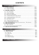
CONTENTS 1. TEST RUN 1-1 EXECUTION PROCEDURE AND EXECUTION PRECAUTIONS............................. 01-01 1-2 CHECK ITEMS BEFORE POWER ON....................................................................... 01-03 1-2-1 Power source inspection...................................................................................... 01-03 1-2-2 Outdoor unit field setting inspection..................................................................... 01-04 1-2-3 Indoor unit field setting inspection..............
CONTENTS 2-9 PROTECTIVE FUNCTION........................................................................................ 02-16 2-9-1 Discharge temperature protection....................................................................... 02-16 2-9-2 High pressure protection...................................................................................... 02-18 2-9-3 Low pressure protection......................................................................................
CONTENTS 4. TROUBLE SHOOTING 4-1 NORMAL OPERATION.............................................................................................. 04-01 4-1-1 Indoor Unit Display.............................................................................................. 04-01 4-1-2 Outdoor Unit Display........................................................................................... 04-02 4-2 ABNORMAL OPERATION.........................................................................................
1.
1. TEST RUN 1-1 EXECUTION PROCEDURE AND EXECUTION PRECAUTIONS Before execution Execution zone decision Confirmation of refrigerant used Preparation of execution drawings Confirmation of installation site Preparations before execution Execution procedure and precautions Reason 1 Check the characteristics of the refrigerant used and grasp the special features of the refrigerant. If refrigerant must be charged, always charge the refrigerant specified for the product. 2 Confirm the product design pressure.
Execution 1 Confirm the additional refrigerant amount with the installation manual, etc. 2 Always take the R410A refrigerant from the cylinder liquid phase and charge it using the gas phase. (Do not lay a cylinder with siphon pipe on its side.) 3 Use an R410A dedicated gauge manifold and charging hose. If taken from the air phase, since the composition of the refrigerant which is charged will change, low performance and abnormal stop will occur easily. Prevent erroneous sealing in of refrigerant.
1-2 Check Items Before Power ON 1-2-1 Power source Inspection sheet Check Item Check contents Judgement Present Status Ref. circuit name: _________________ Power supply 3 / 3W / (208-230V 10%) / 60Hz Master (AJUA ___G) :_____(A) For AJUA72G : 45A For AJUA90G / 120G : 55A Circuit Breaker Size (A) Slave-1(AJUA ___G) :_____(A) Slave-2(AJUA ___G) :_____(A) Leakage current : 100mA, 0.1 sec or less Power Source Power Line Wire Size (mm2) Outdoor Unit Check the breaker capacity vs.
1-2-2 Outdoor unit field setting inspection sheet Check Item Check contents Judgement Present Status No. of outdoor unit for one ref. circuit: ______, Ref. circuit name: _________________ Outlook Appearance Shall be no deformation Serial No.
1-2-4 RB unit field setting Inspection sheet RB Unit Check contents Ref. circuit name: _________________, Ref. address :__(00 Outlook Number of RB units 18.0 kW or less 28.0 kW or less UTP-RU04BH Single type RB unit Maximum 8 units Capacity Each Branch Up to 18.0kW Up to 56.
1-2-5 Transmission wire installation inspection sheet 1/3 Check Item Check contents Judgement Present Status Number of ref. circuit connected in the network system: ______, Ref. addresses: ______________(00 - 99) VRF Network System Transmission wire Is it LonWorks compatible? Outlook / No Maker name? Wire specification 0.
1-2-5 Transmission wire installation inspection sheet 2/3 Check Item Check contents Judgement Present Status Number of ref. circuit connected in the network system: ______, Ref. addresses: ______________(00 Transmission line layout Correct Layout OU (Between RB unit & IU) RB RB IU IU RB Gr.
1-2-5 Transmission wire installation inspection sheet 3/3 Check Item Check contents Judgement Number of ref. circuit connected in the network system : ______, Network Configuration (IU 400 & OU OU number: _____ One System Controller per VRF Network System No. of Touch panel controller (TPC) Connectable Nos. 16 No. of Central RC (CRC) Connectable Nos. 16 No. of Network Convert for Group RC Connectable Nos. 64 No. of Signal Amplifier (SA) TPC: _____ Total 16 Nos.
1-2-6 Piping installation inspection sheet 1/2 Check Item Check contents Judgement Ref. circuit name : _________________________________, Outlook Present Status Ref. address:______________ (00 99) Insulation & Fastening Insulated without gap & properly fastened (Yes / No) Suction line filter Is there any external filter in the suction line Yes Oil Trap If Distance between OUs 2m , Place oil trap both at suction & at Discharge line Yes / No Not applicable (feet) Total Pipe Length ( 3280ft.
1-2-6 Piping installation inspection sheet 2/2 Check Item Check contents Judgement Ref. circuit name: _______________________________________, Present Status Ref. address: ( (00 99) 2) Connect the IU to the RB unit in order of farthest branch port Correct Not correct Keep free branch port within 2 or less per refrigerant cycle Branch port piping layout For multi type RB (RB branch port vs.
1-2-7 Refrigerant charge amount inspection sheet Check Item Check contents Judgement Ref. circuit name: ____________________________, Ref. address :________(00 OU Model Name Outdoor Unit AJUA72G / AJUA90G / AJUA120G @ 6.35mm Connecting Pipe 99) Additional Refrigerant Amount for OU (kg) AJ*A72G / AJ*A90G / AJ*108G : 6.31lbs / 3.0kg Liquid Pipe Length Additional Charged Refrigerant Present Status Additional Refrigerant Amount based on the liquid pipe length (lbs) (ft) For pipe diameter 6.
1-3 Check Items After Power ON Overview of system operation check procedure Step-1: Connect Service Tool PC to the VRF VR-II system. Do scaning of refrigerant system which should be commissioned. Step-2: Compare the number of installed units (OU, RB Group and IU) with the System List data obtained from the Service Tool. Step-3: Operate all Indoor Units under Test Mode Cooling (Select Test mode either cool or heat based on ambient temperature.).
1-3-2 Error indication check sheet 2/2 Check Contents Judgement Ref. circuit name ________________________, Ref.
1-3-4 Transmission line connection check sheet Note: The following check method by using test-run is necessary for checking of incorrect transmission wire connection. Check Contents Check items Checking method Ref. circuit : Name _________________, Judgement Present Status Ref.
1-3-5 Operation check sheet Check Contents Refrigerant Circuit : Name _________________, Judgement Address ________(00 Present Status 99) Degree of sub-cool at OU sub - cooler side should be, 9F TSC 36 F(5 C Tsc 20 C) AND Pulse value EEV3 should be, EEV3 400P Test-run operation Cooling mode Tsc EEV3 P Psi(MPa) Yes / No Suction refrigerant pressure should be, Ps 1.2MPa) 102psi Ps 174psi( 0.7MPa Ps Psi(MPa) Yes / No Yes / No Yes / No Yes / No Yes / No Yes / No Tshe 9 F) IU refg.
1-4 Test Run Operation 1-4-1 Test Run From Outdoor unit PC Board All the indoor units connected to the outdoor unit can be test-operated by push button setting. (Only for master unit) SWITCH POSITION POWER MODE ERROR LED101 (GREEN) LED102 (RED) LED105 7 Segment LED Lamp LED104 MODE /EXIT SELECT ENTER SW107 SW108 SW109 Push button switch Outdoor unit printed circuit board TEST RUN SETTING For a detailed description of push button operation, refer to the [D&T manual Chapter 6.
1-4-2 Test Run From Remote Controller UTY - RNK 1. Standard wired remote controller Stop the indoor unit. Push the button and button simultaneously for more than two seconds. The air conditioner will start to conduct a test run and " " will display on the remote controller display. However, the , setting button does not have function, but all other buttons, displays, and protection functions will operate. SET TEMP. Perform the test operation for 60 minutes.
UTY - DTG 4. Touch panel controller (1) Select the objective you want to test run. Select the objective icon or list at the monitor screen. (Multiple selections is possible) Select all the devices registered as objectives by pressing "Select All" on the monitor screen. (2) After objective selection at (1), switch to the by pressing "Operation".
UTY - RNR 6. 2-wire type wired remote controller (1) Press "Menu" on the monitor screen. the < Main Menu screen > is displayed. (2) Press "Next Page" and press "Maintenance" (3) Press "Next Page" and press "Test Run". the is displayed. (4) Press "OK" The test run continues for 60 minutes. To interrupt test run before it is complet, return to the "Monitor Mode Screen", and press ON/ OFF.
1-5 TEST RUN CONTROL 1. When the test run signal is transmitted from standard wired, wireless remote controller, simple remote controller, transmitted netwwork, and outdoor unit. (1) The test run operation starts and the electric expansion valve is controlled to a maximum flow, regardless of the temperature condition. (2) Frost prevention operation has priority over item(1).
1-6 Field Setting And Monitor Mode List for Outdoor unit Classification Push switch on outdoor unit PCB ITEM CODE No.
Classification ITEM CODE No. Push switch on outdoor unit PCB Install 00 Pipe length setting Setting mode Correction 10 Sequential start shift 11 Cooling capacity shift 12 Heating capacity shift [ F2 ] ITEM CODE No.
Classification Push switch on outdoor unit PCB Low noise setting 1 ITEM CODE No. 40 41 42 Setting mode [ F2 ] Change of function 3 60 ITEM CODE No. Setting Mode Capacity priority setting (in low noise mode) Low noise mode setting Low noise mode operation level setting Back up operation 61,62,63 Forbidden Change of function 4 70 Electricity meter No. setting 1 (Set the ones digit and tens digit of the No of the electricity meter connected to CN135.) 71 Electricity meter No.
Classification Push switch on outdoor unit PCB Forced operation Function mode [ F3 ] ITEM CODE No.
1-7 Field Setting / Function Setting for Indoor unit Classification Indoor unitfield setting setting by remote controller Address Filter Airflow ITEM CODE No. ITEM CODE No.
Classification Indoor unit field setting setting by remote controller Correction Change of function 1 Change of function 2 ITEM CODE No.
1-8 Field Setting / Function Setting for Outdoor air unit Classification Indoor unit field setting setting by remote controller Address Filter Airflow ITEM CODE No. ITEM CODE No. Setting Mode 00 02 11 Indoor unit address Refrigerant circuit address Filter indicator Interval 13 Filter sign display 26 Static Pressure setting - Outdoor air unit Only The Range of static pressure is different from one model to other.
2.
2. OUTDOOR UNIT 2-1 REFRIGERANT CIRCUIT Outdoor unit SV4 TH7 GAS LINE (High pressure) TH9 HPS 4WV 1 HEX1 EEV1 HPSW1 TH1 SV1 OS TH8 TH3 EEV3 TH10 RCV LPS HEX2 4WV 2 LIQUID LINE EEV2 TH4 SCHEX TH5 CMP1 (INV) FP SV2 TH11 FAN1 TH2 CMP TH6 ACM GAS LINE (Low pressure) ACM SV3 Indoor unit1 : Capillary TH21 : Strainer FP : Fusible plug Operation temp. 165 F (75 C ) FAN21 TH24 TH22 EEV21 HEX21 RB unit1 SV D1 SV B2 SV S1 SV B1 SVS2 Function No.
2-1-1 REFRIGERANT CIRCUIT for Outdoor air unit Outdoor air unit (AAUA48/ 96TLAV) 59 TH25 54 FAN21 51 56 TH24 TH22 EEV21 HEX21 57 53 52 TH21 58 Outdoor air unit (AAUA72TLAV) 59 TH25 55 54 FAN21 51 FAN22 56 TH24 TH22 EEV21 HEX21 57 53 52 TH21 58 : Capillary : Strainer No. Part name Function 51 Heat exchanger outlet thermistor Detects the temperature of refrigerant 52 Suction airflow temp.
2-2 INPUT / OUTPUT LIST Input / output or kind of detail Control range Heat exchanger 1 gas temp. sensor Heat exchanger 2 gas temp sensor Heat exchanger 1 liquid temp. sensor Heat exchanger 2 liquid temp.
2-3 Heat Recovery Operation controlling 2-3-1 Operation mode selection and controlling Under Heat Recovery operation, the heat balance for the system is controlled based on the Target High pressure and the Target low pressure. By changing compressor rotation speed or changing Heat exchange capacity, the system can maintain the good heat balance. The target High pressure value and the target low pressure value in the target range are decided by the outdoor unit's operation mode (Condensor or Evaporator).
2-4-2 Compressor speed control (1) Speed range and controlling - On operation range: 20 - 115 rps * - Changing interval: 60 sec. - When the multi connection outdoor unit has the same type of compressor, all of compressors rotational speed are controlled with the same speed at the normal operating condition. - All of the outdoor unit compressors must start at the start-up process.
2-4-3 Capacity Control (1) Capacity of compressor operation The inverter compressor is able to control the amount of required refrigerant circulation in details. [rps] 0.
2-4-4 Compressor Sequence Operation Make starting sequence and start and stop of the compressors in accordance with the below sequence.
2-5 HEAT EXCHANGER CAPACITY CONTROL 2-5-1 Operation mode selection and controlling Under The heat exchanger capacity is controlled using the 4WV, fan, and EEV according to the target high and low pressures. The method for changing the capacity of the heat exchanger differs depending on the operation mode.
2-6 FAN CONTROL 2-6-1 Cooling / Cooling Main Operation The outdoor fan speed at start up is 300 rpm Fan step 16 15 14 13 12 11 10 9 8 7 6 5 4 3 2 1 0 Fan speed (rpm) S-Chassis 880 860 810 720 620 500 420 360 320 300 intermittent 6 intermittent 5 intermittent 4 intermittent 3 intermittent 2 intermittent 1 0 L-Chassis 920 870 820 720 620 500 420 360 320 300 intermittent 6 intermittent 5 intermittent 4 intermittent 3 intermittent 2 intermittent 1 0 << Ex.
Intermittent fan mode When switched from normal fan step to intermittent fan step, always start from 300rpm/7sec. When there was a change during intermittent step 1-6, switching is performed at the time the current speed duration time reaches time-up.
2-7 EXPANSION VALVE CONTROL The EEV controls the flow of refrigerant Control range Contrl and detection Operation mode EEV 1 EEV 2 EEV 3 Cooling Cooling Main Heating Heating Main Cooling Cooling Main Heating Heating Main operation range - Liquid Pressue control (TH4) - HEX balance (TH9,TH10) "TH9 52- 480 pulses 0 pulses 11 - 480 pulses 0 pulses 0- 500 pulses 0 pulses TH10" - SH control (TH7,TH8 - LPS ) "Target SH: 8 F (4 C) " - Protection (TH1) (LPS) - SH control (TH6 - LPS ) "Target SH: 8 F (
2-8 SPECIAL OPERATION 2-8-1 Oil Recovery operation (1) Purpose of the operation The amount of refrigerant lubricant oil which has been transported to the indoor units and the connection pipe with the refrigerant will become large as the operation time of compressor increases. It is necessary to recover the oil back into the outdoor unit for a certain time interval in order to prevent compressors from damaging due to lack of lubrication oil.
2-8-3 Defrost Operation Control < Defrosting start condition > Accumulated heating operation time is 40 minutes or longer (Accumulated heating operation time is reset at the end of cooling operation or defrosting operation.) And One of Heat-Ex satisfies condition Condition or or below : Accumulated operating time is 150 minutes* or longer: "Heat exchange liquid temperature (TH9 and TH10) *75 minutes: when indoor unit connection capacity Condition 28.4°F ( -2°C)" 90% at 1 outdoor unit connection.
< Operating state of each part during defrosting operation > Actuator Preparation process Finishing process On Defrost operatiom Compressor All compressor operaiotn Stop All compressor start All compressor operaiotn Stop Heat Ex(4WV) Change Condensor (OFF) Cndensor (OFF) Keeps the operation mode FAN Stops Stops Stops EEV1 EEV2 0 pls EEV1: 300 -> 200 pls EEV2: 480 -> 330 pls 0 pls EEV3 0 pls 100 - 500 pls 0 pls SV1,SV2 Open (Balancing) Close Open [ STEP 1 ] All compressors sart th
2-8-4 Low noise mode When the low noise mode setting ON from Push SW or External input or System controller Input, the outdoor unit operates in the low noise mode as follows. « Setting and corresponding operations » Low noise mode setting External Input (CN131) or (Push SW) on Master O.
2-8-5 Snow Falling Protection Fan mode - Default Setting The fan rotates compulsorily at the maximum speed when the outdoor temperature becomes 41 F(5 C) or less The fan is rotated for 1 minute at the fan step upper limit at the interval set by PUSH SW. This mode ends when the outdoor temperature becomes 44.6 F (7 C) or more or operation starts.
2-9 PROTECTIVE FUNCTION 2-9-1 Discharge temperature protection Protective function Detect device Discharge temperature protection 1 Discharge temp. sensor Cool Heat Display Starting conditions Release conditions Cooling/Cooling Main: Discharge temperature above 203°F(95°C) Below 194°F (90°C) Heating/Heating Main: Discharge temperature above 216°F(102°C) Below 207°F (97°C) Operation EEV3 + 30pls/30 sec. Discharge temperature protection 2 Discharge temp.
Discharge temperature protection -SummaryProtection controlling range in Cooling mode S R R 176 80 S 194 90 203 95 S DTP2: Outdoor unit rotation excution S R R DTP COMP STOP: Error Indication DTP3: limited Compressor speed controlling DTP1: EEV3 Liquid injection controlling 212 100 221 105 225 107 239 115 (F) ( C) Note: Target pressure controlling will be cancelled when the temperature is in the range color orange.
2-9-2 High pressure protection Protective function Detect device Cool Heat Display Start condition Release condition Operation High pressure protection 1 High pressure sensor Above 573psi (3.94MPa) 60 sec. elapsed and Below 538psi (3.70MPa) SV2 =>ON High pressure protection 2 High pressure sensor Pattern 1 Above 495 (539)* psi (3.40 (3.70)* MPa) 60 sec. elapsed and Below 471 (515)*psi (3.24 (3.54)* MPa) SV2 =>ON 180 sec. elapsed and Pattern 2 Below 486 (530)*psi Above 509 (553)*psi (3.34 (3.
High pressure protection -SummaryProtection controlling range in cooling operaing mode S R R HPP Stop2 : Error Indication E A 42 S R HPP Stop1: Error Indication E A 41 S S Abnromal HP protection ( Pattern 2) : Compressor rotation speed lessen 18.5 rps (-15.0 rps) / 30sec. ( ): L-Chassis Abnromal HP protection ( Pattern 1) : Compressor rotation speed rise up prohibit S R R HP Protection 1: SV2 ON 466 509 538 550 567 573 582 611 ( psi ) 3.20 3.50 3.70 3.78 3.90 3.94 4.00 4.
2-9-3 Low pressure protection Protective function Detect device Cool Heat Display Start condition Release condition Operation Low pressure protection 1 Low pressure sensor Below 15psi (0.10MPa) 3minutes elapsed and Above 25psi (0.17MPa) SV1 =>ON Low pressure protection 2 Low pressure sensor 3minutes elapsed and After compressor started above 32psi (0.22MPa) and 3 minutes elapsed and Below 94psi (0.18MPa) Operating Indoor unit EEV forced controlling -Thermo-OFF indoor unit: 450pls.
2-9-4 Heatsink temperature protection Protective function Detect device Cool Heat Display Start condition Release condition Operation Heat sink temperature protection 1 Heatsink temp sensor Above 167°F (75°C) Below 167°F (75°C) Cancel Fan speed step down. Heat sink temperature protection 2 Heatsink temp sensor Above 181°F (83°C) Below 181°F (83°C) Fan speed up 1 step every 2 minutes.
2-9-7 Over current protection Protective function Detect device Cool Heat Display Start condition E941 (permanent stop) Overcurrecnt protection stop Release condition Over current protection circuit detects (Abnormal current) in 5 times during compressor operatng. Inverter PCB Embeded E931 (permanent stop) Over current protection circuit detects (Abnormal current) at the compressor start-up.
2-9-10 Fan Motor, Motor Driver abnormal stop protection Protective function Detect device Fan Motor lock protection stop Display Start condition Embeded device E97. 1 1. When the outdoor fan rotation speed is less than 100rpm in 20seconds after fan motor starts. 2. After the fan motor restarts, and when the condition 1 is repeated consecutively 4 times. Fan Motor temperature protection stop Embeded device E97. 5 1. When the FAN motor failed the operation more than 470rpm. 2.
3.
INDOOR UNIT OPERATION 3-1 FAN CONTROL 3-1-1 Fan Speed Setting Fan speed setting Press the FAN CONTROL button to set the fan speed. AUTO HIGH MED LOW 3-1-2 "AUTO" Position Fan speed zone 1. COOL OPERATION The fan speed is determined automatically in accordance with the condition "(TR(corrected room temperature) - TS (corrected set temperature)" as shown on the right. However, the fan speed zone is determined in the manner as the room temperature increases for the following cases.
3-2 MASTER CONTROL 3-2-1 Operation Mode Control (1) Mode setting Each possible operation mode in each connectable type is controlled as below. Connectable type Cool Dry Custom - Fan Heat Auto Auto Free Cool / Heat Fix Cool / Heat Only Cool X *1 *1 *2 X X : Mode available X : Mode unavailable *1 : Mode available when the priority given to administrative indoor unit. *2 : Mode available between Dry and Cool. RB : I.U = 1 : 1 RB : I.U = 1 : 2 8 RB : I.
(4) Priority mode ( for connectable type ) The purpose of the priority mode is to restrict operation commands (heating, cooling, dry) from the connected indoor units. There are 3 priority modes of Neutral, Cooling Priority, and Heating Priority. The operation modes restricted by each of these modes are as follows: Priority mode Restricted operation mode Neutral No restrictions Cooling priority Heating Heating priority Cooling, dry Priority mode decision methods Method 1.
3-2-1 Operation Mode Control for Outdoor air unit (1) Mode setting Each possible operation mode in each connectable type is controlled as below. Cool Dry Heat Fan Connectable type Free Cool / Heat X Fix Cool / Heat X Only Cool X : Mode available X : Mode unavailable RB : I.U = 1 : 1 RB : I.U = 1 : 2 8 RB : I.U = 0 : 1 (2) Cool and Heat Mode Each operation mode is controlled as below. Outdoor air unit fan motor Cool Heat Fan Operates according to the HIGH MODE setting.
(4) Priority mode ( for connectable type ) The purpose of the priority mode is to restrict operation commands (heating, cooling) from the connected outdoor air units. There are 3 priority modes of Neutral, Cooling Priority, and Heating Priority. The operation modes restricted by each of these modes are as follows: Priority mode Restricted operation mode Neutral No restrictions Cooling priority Heating Heating priority Cooling Priority mode decision methods Method 1.
3-2-2 Auto Changeover Heating / Cooling Operation [Function available Indoor unit(s)] Connectable type Connectable type : All Indoor units : Administrative indoor unit (Management Indoor unit) Refer to the setting Method Setting Method 1. Switch operation mode management to "Management by indoor unit" by RB unit DIP-SW. 2. Set the master indoor unit by wired remote controller. 3. Judge cooling/heating by the difference between the master indoor unit's setting temperature and the room temperature.
3-2-2 Auto Changeover Heating / Cooling Operation for Outdoor air unit [Function available Outdoor air unit(s)] Connectable type Connectable type : All Outdoor air units : Administrative outdoor air unit (Management Outdoor air unit). Refer to the setting Method Setting Method 1. Switch operation mode management to "Management by outdoor air unit" by RB unit DIP-SW. 2. Set the master outdoor air unit by wired remote controller. 3.
3-2-3 Auto Changeover Cooling / Dry Operation [Function available Indoor unit(s)] Connectable type : Cooling Only indoor unit Judge cooling/dry by the difference between the setting temperature and the room temperature. In case of group connection of cooling only indoor unit, the room temperature sensor in wired remote controller manages the operating mode. AUTO CHANGEOVER operation (COOLING ONLY TYPE ) Operation flow chart START TS : Setting temperature NO Room temp.
3-2-4 Custom Auto Heating / Cooling Operation [Function available in follwing conmditions] - Remote controller type: UTY-RNRU - Remote sensor in use - Prohibit the central function from the Central controller *Reccomend CUSTOM AUTO Operation Operation flow chart START T set.C - T set.H 6°F NO YES T set.C: Setting temp. in Cool T set.H: Setting temp. in Heat Room temp. T set.C + 1.0°F YES NO Room temp. Room temp. 1/2 of DB + 3.0°F NO NO Room temp. YES T set.H - 1.
3-2-4 "COOL" Position When using the cooling mode, set the temperature to a value lower than the current room temperature, otherwise the indoor unit will not start the cooling operation and only the fan will rotate. An example for COOLING TEMPERATURE CONTROL time chart (Manual setting) TR Ts +1°F(+0.5°C) Ts Temperature Ts -1°F(-0.5°C) 3Min. Refrigerant flow ON OFF Opening of 100% 0% EEV Indoor fan*1 ON OFF Ts : Corrected setting temperature TR : Corrected room temperature Ts +1°F(+0.
3-2-5 "COOL" Position for Outdoor air unit When using the cooling mode, set the temperature to a value lower than the discharge airflow temperature, otherwise the outdoor air unit will not start the cooling operation and only the fan will rotate. An example for COOLING TEMPERATURE CONTROL time chart (Manual setting) Outdoor temp.
3-3 LOUVER CONTROL (1) ADJUSTING THE DIRECTION OF AIR CIRCULATION Instructions relating to heating ( ) are applicable only to heat pump type outdoor unit. Begin air conditioner operation before performing this procedure. Vertical Air Direction Adjustment This instructions are applicable to "LARGE CEILING TYPE", "UNIVERSAL FLOOR/CEILING TYPE", "CASSETTE TYPE", "WALL MOUNTED TYPE" and "COMPACT WALL MOUNTED TYPE". Example : When set to vertical air direction. Press the VERTICAL AIR FLOW DIRECTION SET button.
Horizontal Air Direction Adjustment This instructions are applicable to "LARGE CEILING TYPE", "UNIVERSAL FLOOR/CEILING TYPE" and "WALL MOUNTED TYPE". Press the HORIZONTAL AIR FLOW DIRECTION SET button. Press the HORIZONTAL AIRFLOW DIRECTION button. The temperature display will change to the horizontal airflow direction setting display. Press the HORIZONTAL AIRFLOW DIRECTION button to change the horizontal louvre position. The position number will appear on the display.
Instructions are applicable to "LARGE CEILING TYPE", "UNIVERSAL FLOOR / CEILING TYPE", "CASSETTE TYPE", "WALL MOUNTED TYPE", and "COMPACT WALL MOUNTED TYPE". About Vertical Airflow SWING Operation Air swing range The SWING operation may stop temporarily when the air conditioner's fan is not operating, or when operating at very low speeds. Air flow direction set The swing operation is not available depending on the model. Please refer to the operating manual for the indoor unit.
3-4 ELECTRONIC EXPANSION VALVE CONTROL 1. Initialization When the power is turned ON. When it has passed the limited time since the last initialization. 2. Operation Control When indoor unit stopping by Thermo-OFF condition. Outdoor unit Condition OFF EEV Condition Cooling Fully closed Heating Slightly open Fully closed When starting up (Cooling) Move to the cooling control base pulse in steps. (Heating) Move to the heating control base pulse in steps.
3-4 ELECTRONIC EXPANSION VALVE CONTROL for Outdoor air unit 1. Initialization When the power is turned ON. When it has passed the limited time since the last initialization. 2. Operation Control When indoor unit stopping by Thermo-OFF condition. Outdoor unit Condition OFF EEV Condition Cooling Fully closed Heating Fully closed Fully closed When starting up (Cooling) Move to the cooling control base pulse in steps. (Heating) Move to the heating control base pulse in steps.
3-6 FUNCTION 3-6-1 Auto Restart The air conditioner restarts with the previous setting operation. 3-6-2 Freeze Prevention Control The icing of the indoor heat exchanger is prevented during the cooling and dry mode operation. (1) Starting Condition Compressor is operation more than 3 minutes. When "Heat exchanger inlet temperature TA" continues *4 minutes or more. Compressor is operation more than 3 minutes. When "Heat exchanger outlet temperature TA" continues 4 minutes or more.
3-6-4 Outdoor temperature protected operation for Outdoor air unit 1. COOL OPERATION The contents of operation is controlled as following based on the suction airflow temperature. a) Operation mode management is made "Management by indoor unit", and outdoor air unit is master indoor unit.
RB UNIT OPERATION 3-7 RB UNIT COMPORNENT 3-7-1 Position of Solenoid coil Single type UTP-RX01AH UTP-RX01BH SV4 SV1 UTP-RX01CH SV4 SV1 SV5 SV4 SV1 SV5 SV6 SV3 SV2 SV3 SV2 SV3 SV2 Multi type UTP-RX04BH SV4 SV5 SV3 SV1 SV4 SV2 SV5 SV3 SV4 SV1 SV3 SV2 SV4 SV1 SV5 SV5 SV3 SV2 SV1 Color of Connector SV1 SV2 SV3 SV4 SV5 SV6 SV2 Green Blue Black White Red Yellow 3-7-2 Position of Solenoid valve ( ) : Indication on the Service Tool Liquid Line EEV CP3 ST SV1 CV (SVD1)
3-7-3 PCBs layout Single type Multi type - Upper side - -Upper side- Main PCB DIP SW SET 1 SV connector SV connector Error indication LED (Red) Power supply indication LED (Green) Transmission PCB1 DIP SW SET 1 DIP SW SET 2 Transmission PCB2 3-7-4 PCB component OU. RB Unit IU. Transmission PCB2 Main PCB Transmission PCB1 Main PCB: Pulse signal communication between Transmission PCB1 and Transmission PCB2 Transmission PCB1: Pulse signal communication between IU.
3-7-4 Solenoid Valve controlling Open / Close operation in Operation SV No. Cooling / Dry mode Heating mode Fan mode / Stop Close Close Open SV1 ( SVD1 ) Discharge Valve Close SV4 - 6 ( SVS ) Suction Valve Open Close SV2 ( SVB2 ) Equalization Valve (Pressurization) Close Close Open SV3 ( SVB1 ) Equalization Valve (Decompression) Open Open Close ( Indication on Service Tool ) Function Open / Close operation in Special operation SV No.
4.
4.
4-1-2 OUTDOOR UNIT DISPLAY Indication type 7 Segment LED Pattern Description Idling(stop) Blank Cooling Mode (Mainly Cooling) "C" OO "L" Heating Mode (Mainly Heating) "H" EA "T" Oil Recovery Operation "O" IL "R" ECOVERY Defrost Operation "D" E "F" ROST Discharge Temp. Protection is stopped "P" ROTECT "1" Refer to Chapter 02. (Outdoor unit operation control) Refer to Chapter 02.
4-2 ABNORMAL OPERATION 4-2-1 Error code Display An Error code is represented by 3 digit characters. The first 2 digit means the subsection Error code, and the last 1 digit means the specifics Error code. Ex.) Indoor unit Network communication Error 14.
4-2-2 Indoor Unit Display Error Indication Flashing Pattern Example : Indoor Unit Main PCB Error (Operation LED : 3 times, Timer LED : 2 times) 1 cycle ON 1.0s Operation LED 0.5s 0.5s 0.5s 0.5s 0.5s 0.5s 3.0s 1.0s OFF ON Timer LED 1.0s 4.0s 0.5s 0.5s 0.5s 0.5s OFF ON 0.1s / 0.1s Filter LED OFF 4-2-3 Outdoor Unit Display LED display POWER MODE ON POWER LED101 OFF ERROR POWER MODE LED : on ERROR LED : blink 0.1sec 0.
4-2-4 Remote Controller Display << SIMPLE REMOTE CONTROLLER >> ERROR CODE DISPLAY Error code If an error occurs, the following display will be shown. (“ “ will appear in the set room temperature display.) “ is displayed, immediately contact authorized If “ service personnel. Faulty unit No. (Remote controller address) Ex. Error code display << WIRED REMOTE CONTROLLER 3 wire type>> ERROR CODE DISPLAY If an error occurs, the following display will be shown.
4-2-5 Trouble shooting index - Error code List 1/2 Display Target B Display Target A Simple Wired remote controller 2 / 3 wires Wired remote controller Indoor unit LED brinking times, " 1st figure: Operation LED, 2nd figure: Timer LED" * : No Display Display Display Target A Target B A: LED 10 times Blinks J: LED 13 times Blinks Error Contents < Subsection > 9 U 1 3 Communication Error between Outdoor unit 1 4 1 4 1 6 Network Communication Error * 1 4 Group Remote controller Central Remote cont
4-2-5 Trouble shooting index - Error code List 2/2 Display Target A Simple Wired remote controller 2 / 3 wires Wired remote controller Indoor unit LED brinking times, " 1st figure: Operation LED, 2nd figure: Timer LED" * : No Display A: LED 10 times Blinks J: LED 13 times Blinks 7 seg. Display on Outdoor unit Controller PCB Display Target D Service Tool U: LED 15 times Blinks Display Target C Error Contents < Supecifics > Display Target D Trouble shooting No. 7 4 Outdoor temp. Sensor Error 7 4.
4-2-7 TROUBLE LEVEL OF SYSTEM << System Condition when Outdoor Unit Error is occurred >> Trouble Level 1 System Condition Outdoor unit Condition System is not stopped compulsorily Abnormal LED indication Operation continues Outdoor unit does not stop System is compulsorily stopped (*4) System is compulsorily stopped Abnormal LED indication Outdoor unit stop 2 Not indicated on Indoor Unit and Peripheral unit. Indicated on Service Tool. Indicated on Indoor Unit (*1) and Peripheral unit.
4-2-8 ERROR HISTORY MODE When the abnormality occurred, the Outdoor unit memorizes the history of error codes up to 10 and it can be displayed on 7 segments LED. It is an effective means to examine abnormality that occurred in the past. *The error history can be cleared by setting to F3-30. Refer to the following for the procedure.
4-2-9 TROUBLE SHOOTING WITH ERROR CODE Trouble shooting 1 INDOOR UNIT Error Method: Wired Remote Controller Communication Error E12.1 Indicate or Display: Outdoor Unit : E.5 U.1 Indoor Unit : Operation LED 1 times Flash, Timer LED 2 Times Flash, Filter LED Continuous Flash.
Trouble shooting 2 INDOOR UNIT Error Method: E12.2 Wired Remote Controller signal Error Indicate or Display: Outdoor Unit : E.5 U.1, Indoor Unit : Operation LED 1 times Flash, Timer LED 2 Times Flash, Filter LED Continuous Flash. Remote Controller : 1 2 Detective Actuators: Detective details: Indoor unit Controller PCB circuit Wired Remote Control (3 wire type) More than 1 time of Token (Communication between wired remote controllers) is received, but it was not received more than 1 minute.
Number excess of device in Wired remote contorller system (2 Wires RC) Indicate or Display: Outdoor Unit : E.5 U.1 Indoor Unit : Operation LED 1 times Flash, Timer LED 2 Times Flash, Filter LED Continuous Flash. Error Code : 12 Detective Actuators: Detective details: Wired remote controller ( 2-Wire ) Indoor unit Controller PCB circuit When the number of connecting Indoor unit and Remote controller in one RCgroup exceeds more than 32 units. Trouble shooting 3 INDOOR UNIT Error Method: E12.
Trouble shooting 4 E1 3. 1 OUTDOOR UNIT Error Method: Communication Error Between Outdoor unit Indicate or Display: Outdoor Unit : E. 1 3. 1 Indoor Unit : Operation LED 9 times Flash, Timer LED 15 Times Flash, Filter LED Continuous Flash.
Trouble shooting 5 E14.1 OUTDOOR UNIT Error Method: Outdoor Unit Network Communication 1 Error Indicate or Display: Outdoor Unit : E. 1 4. 1 Indoor Unit : No display / Operation LED 1 times Flash, Timer LED 4 Times Flash, Filter LED Continuous Flash. Error Code : 1 4 / 1 6 / 1 4. 1 / 1 4. 3 * * Indoor unit indicates No display or 1 4 Peripheral device indicates 1 4 or 16. Detective Actuators: Outdoor unit Main PCB Detective details: DIP-SW SET4-1 is OFF.
Trouble shooting 6 E14. 2 OUTDOOR UNIT Error Method : Outdoor Unit Network Communication 2 Error Indicate or Display: Outdoor Unit : E. 1 4. 2 Indoor Unit : Operation LED 9 times Flash, Timer LED 15 Times Flash, Filter LED Continuous Flash. / Operation LED 1 times Flash, Timer LED 4 Times Flash, Filter LED Continuous Flash. * Error Code : 9 U / 1 4 / 1 6 / 1 4. 1 / 1 4. 2 / 1 4.
Trouble shooting 7 E14. 3 INDOOR UNIT Error Method: Indoor unit Network communication Error Indicate or Display: Outdoor Unit : E.1 4. 1 / 1 4. 2 * Indoor Unit : Operation LED 1 times Flash, Timer LED 4 Times Flash, Filter LED Continuous Flash. Error Code : 1 4 / 1 6 / 9 U / 14.1 / 14.2 / 14.3 * * Outdoor unit indicates 1 4.1 or 1 4.2 (No communication from 14.
Trouble shooting 8 E14. 5 OUTDOOR UNIT Error Method: The number of Indoor unit shortage Error Indicate or Display: Outdoor Unit : E.1 4. 5 Indoor Unit : Operation LED 9 times Flash, Timer LED 15 Times Flash, Filter LED Continuous Flash. / No display (When DIP-SW4-1 is OFF.) Error Code : 9 U / 1 4 / 1 6 / 1 4. 5 / 1 4.
Trouble shooting 9 E16. 1 INDOOR UNIT Error Method: Transmission PCB Connection Error Indicate or Display: Outdoor Unit : E.1 4.1, 1 4.2 * Indoor Unit : Operation LED 1 times Flash, Timer LED 6 Times Flash, Filter LED Continuous Flash. Error Code : 16* * Outdoor unit indicates 1 4.1 or 14.2 (No communication from Indoor unit) Peripheral device indicates 1 6 ( 1 6.4 Error) Service Tool indicates 14.
Trouble shooting 10 E16. 4 INDOOR UNIT Error Method: Communication Error Between Controller and Indoor unit Indicate or Display: Outdoor Unit : No Display Indoor Unit : No Display Error Code : 1 6 (Peripheral Unit ) Detective Actuators: Detective details: Indoor unit Controller PCB circuit Indoor unit Communication PCB When the cut-off of network communication is detected (more than 90 seconds passed since the last receipt of Outdoor unit signal). Forecast of Cause : 1. Outside cause 2.
Address Duplication in Wired remote contorller system Indicate or Display: Outdoor Unit : E.5 U.1 Indoor Unit : Operation LED 2 times Flash, Timer LED 6 Times Flash, Filter LED Continuous Flash. Error Code : 2 6 Detective Actuators: Detective details: Trouble shooting 11 INDOOR UNIT Error Method: E26. 4 Wired remote controller ( 2-Wire ) Indoor unit Controller PCB circuit When the duplicated address number exists in one RCgroup Forecast of Cause : 1. Wrong wiring of RCgroup 2.
Address setting Error in Wired remote contorller system Indicate or Display: Outdoor Unit : E.5 U.1 Indoor Unit : Operation LED 2 times Flash, Timer LED 6 Times Flash, Filter LED Continuous Flash. Error Code : 2 6 Detective Actuators: Detective details: Trouble shooting 12 INDOOR UNIT Error Method: E26. 5 Wired remote controller ( 2-Wire ) Indoor unit Controller PCB circuit When the address number set by auto setting and manual setting are mixed in one RC group Forecast of Cause : 1.
Trouble shooting 13 E28. 1 OUTDOOR UNIT Error Method: Auto Address Setting Error Indicate or Display: Outdoor Unit : E. 28. 1 Indoor Unit : No Display Error Code : No Display * Service tool does not indicate the Error code << After Indoor unit Auto Adress setting >> Detective details: Detective Actuators: When none of the connected indoor units answers during auto address And when abnormal answer signal is input. Outdoor unit Main PCB Forecast of Cause : 1. Indoor unit power supply defective 3.
Trouble shooting 14 E28. 4 OUTDOOR UNIT Error Method: Signal Amplifier Auto Address Error Detective Actuators: Outdoor unit Main PCB Forecast of Cause : Indicate or Display: Outdoor Unit : E. 2 8. 4 Indoor Unit : No Display Error Code : No Display *Service tool does not indicate the Error Detective details: When abnormal answer signal is input during signal amplifier auto address 1. Signal amplifier power supply defective 3. Signal amplifier auto address wrong setting 2.
Connection unit number error (Indoor unit in Wired remote controller system) Indicate or Display: Outdoor Unit : E.5 U.1 Indoor Unit : Operation LED 2 times Flash, Timer LED 9 Times Flash, Filter LED Continuous Flash. Error Code : 2 9 Detective Actuators: Detective details: Trouble shooting 15 INDOOR UNIT Error Method: E29. 1 Wired remote controller ( 2-Wire ) Indoor unit Controller PCB circuit When the number of connecting indoor units are out of specified rule. Forecast of Cause : 1.
Trouble shooting 16 INDOOR UNIT Error Method: Connection unit number error (Remote controller) Detective Actuators: Wired remote controller ( 2-Wire ) E29. 2 Indicate or Display: Outdoor Unit : No Display Indoor Unit : No Display Error Code : 29 Detective details: When the number of connecting remote controller are out of specified rule. Forecast of Cause : 1. Wrong wiring / Wrong number of connecting RC in RCgroup 2.
INDOOR UNIT Error Method: Indoor unit Power Frequency Abnormal Indicate or Display: Outdoor Unit : E.5 U.1 Indoor Unit : Operation LED 3 times Flash, Timer LED 1 Times Flash, Filter LED Continuous Flash. Error Code : 3 1 Detective Actuators: Detective details: Indoor Unit Controller PCB Circuit When 5 continuous failures occurred at Power frequency test. Trouble shooting 17 E31. 3 Forecast of Cause : 1. Outside cause 2. Installation failure 3. Defective connection of electric components 4.
Trouble shooting 18 E32. 1 INDOOR UNIT Error Method: Indoor unit PCB Model Information Error Detective Actuators: Indoor Unit Controller PCB Circuit Indicate or Display: Outdoor Unit : E.5 U.1 Indoor Unit : Operation LED 3 times Flash, Timer LED 2 Times Flash, Filter LED Continuous Flash. Error Code : 3 2 Detective details: 3 continuous failure of lead test of EEPROM at Power ON, or Apparent Model information error from EEPROM.
Trouble shooting 19 INDOOR UNIT Error Method: E32. 3 Indoor unit EEPROM Access Error Indicate or Display: Outdoor Unit : E.5 U.1 Indoor Unit : Operation LED 3 times Flash, Timer LED 2 Times Flash, Filter LED Continuous Flash. Error Code : 3 2 Detective Actuators: Detective details: Indoor Unit Controller PCB Circuit When 3 continuous failure occurred on lead test of EEPROM. Forecast of Cause : 1. Outside cause 2. Defective connection of electric component 3.
Trouble shooting 20 INDOOR UNIT Error Method: E3A. 1 Indoor unit communication circuit (WRC) microcomputers communication Error Detective Actuators: Wired remote controller ( 2-Wire ) Indoor unit Controller PCB circuit Indicate or Display: Outdoor Unit : E.5 U.1 Indoor Unit : Operation LED 3 times Flash, Timer LED 10 Times Flash, Filter LED Continuous Flash.
Trouble shooting 21 INDOOR UNIT Error Method: E41. 1 Inlet air temp. Sensor Error Indicate or Display: Outdoor Unit : E.5 U.1 Indoor Unit : Operation LED 4 times Flash, Timer LED 1 Times Flash, Filter LED Continuous Flash. Error Code : 4 1 Detective Actuators: Detective details: Indoor Unit Controller PCB Circuit Inlet air temp Sensor When Inlet air temp. sensor open or shortage is detected Forecast of Cause : 1. Connector defective connection 2. Sensor defective 3.
Trouble shooting 22 E42. 1 INDOOR UNIT Error Method: Indoor unit Heat Ex. inlet temp. sensor Error Indicate or Display: Outdoor Unit : E.5 U.1 Indoor Unit : Operation LED 4 times Flash, Timer LED 2 Times Flash, Filter LED Continuous Flash. Error Code : 4 2 Detective Actuators: Detective details: Indoor Unit Controller PCB Circuit Heat Exchanger Inlet temp. Sensor When open or shorted Heat Exchanger Inlet temp. sensor is detected Forecast of Cause : 1. Connector defective connection 2.
Trouble shooting 23 E42. 3 INDOOR UNIT Error Method: Indoor unit Heat Ex. outlet temp. Sensor Error Indicate or Display: Outdoor Unit : E.5 U.1 Indoor Unit : Operation LED 4 times Flash, Timer LED 2 Times Flash, Filter LED Continuous Flash. Error Code : 4 2 Detective Actuators: Detective details: Indoor Unit Controller PCB Circuit Heat Exchanger Outlet Temp. Sensor When open or shorted Heat Exchanger outlet temp. sensor is detected Forecast of Cause : 1. Connector defective connection 2.
Trouble shooting 24 E51. 2 INDOOR UNIT Error Method: Indoor Unit Fan Motor 1 rotation speed Error Indicate or Display: Outdoor Unit : E.5 U.1 Indoor Unit : Operation LED 5 times Flash, Timer LED 1 Times Flash, Filter LED Continuous Flash. Error Code : 5 1 Detective details: Detective Actuators: Indoor Unit Controller PCB Circuit Indoor Fan Motor When the FAN motor feed back rotation value which is detecting on the controller PCB becomes 0 and lasts for more than 1 minute at motor opera tion condition.
Trouble shooting 25 INDOOR UNIT Error Method: E52. 1 Coil 1 (Expansion valve ) Error Detective Actuators: Indoor unit controller PCB Indicate or Display: Outdoor Unit : E.5U.1 Indoor Unit : Operation LED 5 times Flash, Timer LED 2 Times Flash, Filter LED Continuous Flash. Error Code : 5 2 Detective details: When the EEV1 drive circuit is open circuit Forecast of Cause : 1. EEV1 coil lose connection 2. EEV1 wire(s) cut or pinched 3. Defective EEV1 coil 4. Controller PCB (DC 12V) output abnormal 5.
Trouble shooting 26 INDOOR UNIT Error Method: E53. 1 Indoor unit Drain pump Error Indicate or Display: Outdoor Unit : E.5 U.1 Indoor Unit : Operation LED 5 times Flash, Timer LED 3 Times Flash, Filter LED Continuous Flash. Error Code : 5 3 Detective Actuators: Detective details: Indoor Unit Controller PCB Circuit Float Switch When Float switch is ON for more than 3 minutes. Forecast of Cause : 1. Drain Installation 2. Drain pipe line blockage 3. Float switch defective 4. Shorted connector/wire 5.
Trouble shooting 27 E61. 5 OUTDOOR UNIT Error Method: Outdoor Unit Reverse Phase, Missing Phase Wire Error Indicate or Display: Outdoor Unit : E. 6 1. 5 Indoor Unit : Operation LED 9 times Flash, Timer LED 15 Times Flash, Filter LED Continuous Flash. Error Code : 9U / 61 Detective Actuators: Detective details: Reverse phase prevention circuit detected reversed phase input or input was not normal at the time of power ON.
Trouble shooting 28 E62. 3 OUTDOOR UNIT Error Method: Outdoor Unit EEPROM Access Error Detective Actuators: Indicate or Display: Outdoor Unit : E. 6 2. 3 Indoor Unit : Operation LED 9 times Flash, Timer LED 15 Times Flash, Filter LED Continuous Flash. Error Code : 9U / 62 Detective details: Access to EEPROM failed due to some cause after outdoor unit started. Outdoor unit Main PCB Forecast of Cause : 1. Noise, momentary open, voltage drop Check Point 1-1 : Turn the power on again 2.
Trouble shooting 29 E62. 6 OUTDOOR UNIT Error Method: Inverters Communication Error Detective Actuators: Detective details: Communication not received from Inverter PCB for 10 seconds or more Outdoor unit Main PCB Forecast of Cause : Indicate or Display: Outdoor Unit : E. 6 2. 6 Indoor Unit : Operation LED 9 times Flash, Timer LED 15 Times Flash, Filter LED Continuous Flash. Error Code : 9U / 62 1. Noise 2. Main PCB to Inverter PCB wiring connection defective 3. Main PCB defective 4.
Trouble shooting 30 E62. 8 OUTDOOR UNIT Error Method: EEPROM data corrupted error Detective Actuators: Detective details: Set contents sum value memorized in EEPROM and sum value calculated based on the set contents read from EEPROM do not match * Regarding the sum value, only the contents set in the push button SW setting mode (F2) shall be the objective. Outdoor unit Main PCB Forecast of Cause : Indicate or Display: Outdoor Unit : E. 6 2.
Trouble shooting 31 E63. 1 OUTDOOR UNIT Error Method: Inverter Error Detective Actuators: Indicate or Display: Outdoor Unit : E. 6 3. 1 Indoor Unit : Operation LED 9 times Flash, Timer LED 15 Times Flash, Filter LED Continuous Flash. Error Code : 9U/ 63 Detective details: Error information received from Inverter PCB. Inverter PCB When "Inverter PCB short interruption detection" or "Rush current limiting resistor temp. rise protection" occurs, Inverter error also occurs. Forecast of Cause : 1.
Trouble shooting 32 E67. 2 OUTDOOR UNIT Error Method: Inverter PCB short interruption Error Indicate or Display: Detective Actuators: Detective details: Inverter PCB Outdoor Unit : E. 6 7. 2 Indoor Unit : No Display Error Code : No display ''Short interruption" received from Inverter PCB Forecast of Cause : 1. Noise, momentary power failure, voltage drop 2. Magnetic Relay (for Inverter) coil side wiring disconnection, open 3.
Rush Current Limiting Resistor Temp Rise Protection Indicate or Display: Outdoor Unit : E. 6 8. 2 Indoor Unit : Operation LED 9 times Flash, Timer LED 15 Times Flash, Filter LED Continuous Flash. Error Code : 9U / 68 Detective Actuators: Detective details: Trouble shooting 33 E68. 2 OUTDOOR UNIT Error Method: "Protection stop by "Rush current limiting resistor temperature rise detection'' of inverter PCB" was generated 2 times. Inverter PCB Forecast of Cause : 1.
Trouble shooting 34 E69. 1 OUTDOOR UNIT Error Method: Outdoor Unit Transmission PCB Parallel Communication Error Indicate or Display: Outdoor Unit : E. 6 9. 1 Indoor Unit : Operation LED 9 times Flash, Timer LED 15 Times Flash, Filter LED Continuous Flash. / Operation LED 1 time Flash, Timer LED 4 Times Flash, Filter LED Continuous Flash. Error Code : 9 U / 6 9 / 1 4 / 14.1 / 14.3* *When this error occurs on the Slave outdoor unit, Error code 69.1 is transfered to each device on the network.
Trouble shooting 35 E71. 1 OUTDOOR UNIT Error Method: Discharge Temp. Sensor 1 Error Detective Actuators: Indicate or Display: Outdoor Unit : E. 7 1. 1 Indoor Unit : Operation LED 9 times Flash, Timer LED 15 Times Flash, Filter LED Continuous Flash. Error Code : 9U / 71 Detective details: Discharge temp. sensor 1 short detected Discharge temp. sensor 1 open detected after compressor 1 operated continuously for 5 minutes or more Discharge temp. sensor 1 Forecast of Cause : 1.
Trouble shooting 36 E72. 1 OUTDOOR UNIT Error Method: Compressor Temp Sensor 1 Error Detective Actuators: Indicate or Display: Outdoor Unit : E. 7 2. 1 Indoor Unit : Operation LED 9 times Flash, Timer LED 15 Times Flash, Filter LED Continuous Flash. Error Code : 9U / 72 Detective details: Compressor temp. sensor 1 Forecast of Cause : Compressor temp. sensor 1 short detected Compressor temp. sensor 1 open detected after compressor 1 operated continuously for 5 minutes or more 1.
Trouble shooting 37 E73.4 OUTDOOR UNIT Error Method: Heat Ex.1 Gas Temp Sensor Error Detective details: Detective Actuators: Heat ex.1 gas temp. sensor Forecast of Cause : Indicate or Display: Outdoor Unit : E. 7 3. 4 Indoor Unit : Operation LED 9 times Flash, Timer LED 15 Times Flash, Filter LED Continuous Flash. Error Code : 9U / 73 Heat ex.1 gas temp. sensor short or open detected 1. Connector connection defective, open 2. Sensor defective 3.
Trouble shooting 38 E 73. 5 OUTDOOR UNIT Error Method: Heat Ex.1 Liquid Temp Sensor Error Indicate or Display: Outdoor Unit : E. 7 3. 5 Indoor Unit : Operation LED 9 times Flash, Timer LED 15 Times Flash, Filter LED Continuous Flash. Error Code : 9U / 73 Detective Actuators: Detective details: Heat ex.1 liquid temp. sensor Forecast of Cause : Heat ex.1 liquid temp. sensor short or open detected 1. Connector connection defective, open 2. Sensor defective 3.
Trouble shooting 39 E73. 6 OUTDOOR UNIT Error Method: Heat Ex.2 Gas Temp Sensor Error Detective details: Detective Actuators: Heat ex.2 gas temp. sensor Forecast of Cause : Indicate or Display: Outdoor Unit : E. 7 3. 6 Indoor Unit : Operation LED 9 times Flash, Timer LED 15 Times Flash, Filter LED Continuous Flash. Error Code : 9U / 73 Heat ex.2 gas temp. sensor short or open detected 1. Connector connection defective, open 2. Sensor defective 3.
Trouble shooting 40 E73. 7 OUTDOOR UNIT Error Method: Heat Ex.2 Liquid Temp Sensor Error Indicate or Display: Outdoor Unit : E. 7 3. 7 Indoor Unit : Operation LED 9 times Flash, Timer LED 15 Times Flash, Filter LED Continuous Flash. Error Code : 9U / 73 Detective Actuators: Detective details: Heat ex.2 liquid temp. sensor Forecast of Cause : Heat ex.2 liquid temp. sensor short or open detected 1. Connector connection defective, open 2. Sensor defective 3.
Trouble shooting 41 E74. 1 OUTDOOR UNIT Error Method: Outdoor Temp Sensor Error Detective Actuators: Detective details: Outdoor temp. sensor short or open detected Outdoor temp. sensor Forecast of Cause : Indicate or Display: Outdoor Unit : E. 7 4. 1 Indoor Unit : Operation LED 9 times Flash, Timer LED 15 Times Flash, Filter LED Continuous Flash. Error Code : 9U / 74 1. Connector connection defective, open 2. Sensor defective 3.
Trouble shooting 42 E75. 1 OUTDOOR UNIT Error Method: Suction Gas Temp Sensor Error Detective Actuators: Indicate or Display: Outdoor Unit : E. 7 5. 1 Indoor Unit : Operation LED 9 times Flash, Timer LED 15 Times Flash, Filter LED Continuous Flash. Error Code : 9U / 75 Detective details: Suction gas temp. sensor Forecast of Cause : Suction gas temp. sensor short or open detected 1. Connector connection defective, open 2. Sensor defective 3.
Trouble shooting 43 E77. 1 OUTDOOR UNIT Error Method: Heat Sink Temp Sensor Error Detective Actuators: Detective details: Heat sink temp. sensor open/short detected Heat sink temp. sensor Forecast of Cause : Indicate or Display: Outdoor Unit : E. 7 7. 1 Indoor Unit : Operation LED 9 times Flash, Timer LED 15 Times Flash, Filter LED Continuous Flash. Error Code : 9U / 77 1. Connector connection defective, open 2. Sensor defective 3.
Trouble shooting 44 E82. 2 OUTDOOR UNIT Error Method: Sub-cool Heat EX. Gas outlet Temp Sensor Error Indicate or Display: Outdoor Unit : E. 8 2. 2 Indoor Unit : Operation LED 9 times Flash, Timer LED 15 Times Flash, Filter LED Continuous Flash. Error Code : 9U / 82 Detective Actuators: Detective details: Sub-cooling heat ex. gas outlet temp. sensor Forecast of Cause : Sub-cooling heat ex. gas outlet temp. sensor short or open detected. 1. Connector connection defective, open 2. Sensor defective 3.
Trouble shooting 45 E83. 1 OUTDOOR UNIT Error Method: Liquid Pipe Temp. Sensor 1 Error Indicate or Display: Outdoor Unit : E. 8 3. 1 Indoor Unit : Operation LED 9 times Flash, Timer LED 15 Times Flash, Filter LED Continuous Flash. Error Code : 9U / 83 Detective details: Detective Actuators: Liquid pipe temp. sensor 1 Forecast of Cause : Liquid pipe temp. sensor 1 short or open detected 1. Connector connection defective, open 2. Sensor defective 3.
Trouble shooting 46 E83. 2 Indicate or Display: Outdoor Unit : E. 8 3. 2 OUTDOOR UNIT Error Method: Indoor Unit Liquid Pipe Temp. Sensor 2 Error Error Code Detective details: Detective Actuators: Liquid pipe temp. sensor 2 Forecast of Cause : : Operation LED 9 times Flash, Timer LED 15 Times Flash, Filter LED Continuous Flash. : 9U / 83 Liquid pipe temp. sensor 2 short or open detected 1. Connector connection defective, open 2. Sensor defective 3.
Trouble shooting 47 E84. 1 OUTDOOR UNIT Error Method: Current Sensor 1 abnormal Indicate or Display: Outdoor Unit : E. 8 4. 1 Indoor Unit : Operation LED 9 times Flash, Timer LED 15 Times Flash, Filter LED Continuous Flash.
Trouble shooting 48 E86. 1 OUTDOOR UNIT Error Method: Discharge Pressure Sensor Error Detective details: Detective Actuators: When any of the following conditions is satisfied, a discharge pressure sensor error is generated. 1. 30 seconds or more have elapsed since the outdoor unit power was turned on and pressure sensor detected value 0.3V continued for 30 seconds or more 2. 30 seconds or more have elapsed since the outdoor unit power was turned on and pressure sensor detected value 5.0V was detected.
Trouble shooting 49 E86. 3 OUTDOOR UNIT Error Method: Suction Pressure Sensor Error Detective details: Detective Actuators: When any of the following conditions is satisfied, a suction pressure sensor error is generated. 1. 30 seconds or more have elapsed since the outdoor unit power was turned on and pressure sensor detected value 0.06V continued for 30 seconds or more. 2. 30 seconds or more have elapsed since the outdoor unit power was turned on and pressure sensor detected value 5.0V was detected.
Trouble shooting 50 E86. 4 OUTDOOR UNIT Error Method: High Pressure Switch 1 Error Detective Actuators: Indicate or Display: Outdoor Unit : E. 8 6. 4 Indoor Unit : Operation LED 9 times Flash, Timer LED 15 Times Flash, Filter LED Continuous Flash. Error Code : 9U / 86 Detective details: High pressure switch 1 Forecast of Cause : When the power was turned on, "high pressure switch 1: open" was detected. 1. High pressure switch 1 connector disconnection, open 2.
Trouble shooting 51 E93. 1 OUTDOOR UNIT Error Method: Inverter Compressor Start UP Error Detective Actuators: Inverter PCB Indicate or Display: Outdoor Unit : E. 9 3. 1 Indoor Unit : Operation LED 9 times Flash, Timer LED 15 Times Flash, Filter LED Continuous Flash.
Trouble shooting 52 E94. 1 OUTDOOR UNIT Error Method: Trip Detection Detective Actuators: Inverter PCB Indicate or Display: Outdoor Unit : E. 9 4. 1 Indoor Unit : Operation LED 9 times Flash, Timer LED 15 Times Flash, Filter LED Continuous Flash. Error Code : 9U / 94 Detective details: "Protection stop by "overcurrent generation after inverter compressor start processing completed'''' generated consecutively 5 times.
Trouble shooting 53 E95. 5 OUTDOOR UNIT Error Method: Compressor Motor Loss of Synchronization Indicate or Display: Outdoor Unit : E. 9 5. 5 Indoor Unit : Operation LED 9 times Flash, Timer LED 15 Times Flash, Filter LED Continuous Flash.
Trouble shooting 54 E97. 1 OUTDOOR UNIT Error Method: Outdoor Unit Fan Motor Lock Error Detective Actuators: Outdoor unit fan motor Forecast of Cause : Indicate or Display: Outdoor Unit : E. 9 7. 1 Indoor Unit : Operation LED 9 times Flash, Timer LED 15 Times Flash, Filter LED Continuous Flash. Error Code : 9U / 97 Detective details: 1. When outdoor fan rotation speed is less than 100rpm in 20 seconds after fan motor starts, fan motor and compressor stops. 2.
Trouble shooting 55 E97. 5 OUTDOOR UNIT Error Method: Outdoor Unit Fan Motor Temp. Abnormal Indicate or Display: Outdoor Unit : E. 9 7. 5 Indoor Unit : Operation LED 9 times Flash, Timer LED 15 Times Flash, Filter LED Continuous Flash. Error Code : 9U / 97 Detective Actuators: Detective details: 1. When outdoor fan motor cannot operate more than 470rpm, fan motor and compressor stops. 2.
Trouble shooting 56 E97. 9 OUTDOOR UNIT Error Method: Outdoor Unit Fan Motor Driver Abnormal Indicate or Display: Outdoor Unit : E. 9 7. 9 Indoor Unit : Operation LED 9 times Flash, Timer LED 15 Times Flash, Filter LED Continuous Flash. Error Code :9U /97 Detective Actuators: Detective details: Driver PCB Fan motor Main PCB Forecast of Cause : When Driver PCB detects the following abnormalities, the error signal is output.
Trouble shooting 57 E9A.1 OUTDOOR UNIT Error Method: Coil 1 (EEV) Error Detective Actuators: Indicate or Display: Outdoor Unit : E. 9 A. 1 Indoor Unit : Operation LED 9 times Flash, Timer LED 15 Times Flash, Filter LED Continuous Flash. Error Code : 9U/9A Detective details: Coil 1(Expansion valve 1) driver circuit open detected. Main PCB Forecast of Cause : 1. EEV1 coil loose connection 3. Defective EEV1 coil 2. EEV1 wires cut or pinched. 4.
Trouble shooting 58 E9A.2 OUTDOOR UNIT Error Method: Coil 2 (EEV) Error Detective Actuators: Indicate or Display: Outdoor Unit : E. 9 A. 2 Indoor Unit : Operation LED 9 times Flash, Timer LED 15 Times Flash, Filter LED Continuous Flash. Error Code : 9 U / 9A Detective details: Coil 2(Expansion valve 2) driver circuit open detected. Main PCB Forecast of Cause : 1. EEV2 coil loose connection 3. Defective EEV2 coil 2. EEV2 wires cut or pinched. 4.
Trouble shooting 59 E9A.3 OUTDOOR UNIT Error Method: Coil 3 (EEV) Error Detective Actuators: Indicate or Display: Outdoor Unit : E. 9 A. 3 Indoor Unit : Operation LED 9 times Flash, Timer LED 15 Times Flash, Filter LED Continuous Flash. Error Code : 9U/9A Detective details: Coil 3(Expansion valve 3) driver circuit open detected. Main PCB Forecast of Cause : 1. EEV3 coil loose connection 3. Defective EEV3 coil 2. EEV3 wires cut or pinched. 4.
Trouble shooting 60 E9U.2 OUTDOOR UNIT Error Method: Indicate or Display: Outdoor Unit : E. 9 U. 2 (Only for master outdoor unit) Slave Outdoor Unit Error Indoor Unit Error Code : No display / Operation LED 9 times Flash, Timer LED 15 timse Flash Filter LED Continuous Flash : * * Master Outdoor unit : 9 U.
Trouble shooting 61 EA1. 1 Indicate or Display: Outdoor Unit : E. A 1. 1 OUTDOOR UNIT Error Method: Discharge Tempreture 1 Abnormal Indoor Unit Error Code Detective Actuators: Detective details: Discharge temp. sensor 1 Forecast of Cause : : Operation LED 9 times Flash, Timer LED 15 Times Flash, Filter LED Continuous Flash. : 9U / A1 "Protection stop by "discharge temp. 1 115°C (239°F) during compressor 1 operation"" generated 2 times within 40 minutes. 1. 3-way valve not opened 2.
Trouble shooting 62 EA3. 1 Indicate or Display: Outdoor Unit : E. A 3. 1 OUTDOOR UNIT Error Method: Compressor 1 Temperature Abnormal Indoor Unit Error Code Detective Actuators: Compressor temp. sensor 1 Forecast of Cause : : Operation LED 9 times Flash, Timer LED 15 Times Flash, Filter LED Continuous Flash. : 9U / A3 Detective details: "Protection stop by "compressor 1 temp. 115°C (239°F)during compressor 1 operation"" generated 2 times within 40 minutes. 1. 3-way valve not opened 2.
Trouble shooting 63 EA4. 1 Indicate or Display: Outdoor Unit : E. A 4. 1 OUTDOOR UNIT Error Method: High Pressure Abnormal Indoor Unit Error Code Detective Actuators: Judgment from value sensed by discharge pressure sensor Forecast of Cause : : Operation LED 9 times Flash, Timer LED 15 Times Flash, Filter LED Continuous Flash. : 9U / A4 Detective details: "Protection stop by "discharge pressure 580psi(4.00MPa)during operation of any compressor"" generated 3 times within 60 minutes 1.
Trouble shooting 64 EA4. 2 OUTDOOR UNIT Error Method: High Pressure Protection 1 Indicate or Display: Outdoor Unit : E. A 4. 2 Indoor Unit : Operation LED 9 times Flash, Timer LED 15 Times Flash, Filter LED Continuous Flash. Error Code : 9U / A 4 Detective details: Detective Actuators: "Protection stop by "high pressure switch 1 operated during compressor 1 operation"" generated 3 times within 60 minutes High pressure switch 1 Forecast of Cause : 1. 3-way valve not opened 2.
Trouble shooting 65 EA5. 1 OUTDOOR UNIT Error Method: Low Pressure Abnormal Detective Actuators: Indicate or Display: Outdoor Unit : E. A 5. 1 Indoor Unit : Operation LED 9 times Flash, Timer LED 15 Times Flash, Filter LED Continuous Flash. Error Code : 9U / A6 Detective details: Suction pressure sensor "Protection stop by "suction pressure 15psi (0.10MPa)continued for 10 minutes" or "suction pressure 7.25psi(0.
Trouble shooting 66 EA6. 3 OUTDOOR UNIT Error Method: Heat Ex.1 gas temp. Error Detective Actuators: Heat Ex.1 gas temp. sensor (TH7) Forecast of Cause : Indicate or Display: Outdoor Unit : E. A 6. 3 Indoor Unit : Operation LED 9 times Flash, Timer LED 15 Times Flash, Filter LED Continuous Flash. Error Code : 9U / A6 Detective details: Heat Ex.1 gas temp. sensor (TH7) for use as condenser (4way valve1:Off, EEV1:Open) is detected abnormally-low to High pressure saturated temp. for 4 minutes or more. 1.
Trouble shooting 67 EA6. 4 OUTDOOR UNIT Error Method: Heat Ex.2 gas temp. Error Detective Actuators: Heat Ex.2 gas temp. sensor (TH8) Forecast of Cause : Indicate or Display: Outdoor Unit : E. A 6. 4 Indoor Unit : Operation LED 9 times Flash, Timer LED 15 Times Flash, Filter LED Continuous Flash. Error Code : 9U / A6 Detective details: Heat Ex.2 gas temp. sensor (TH8) for use as condenser (4way valve2:Off, EEV2:Open) is detected abnormally-low to High pressure saturated temp. for 4 minutes or more. 1.
Trouble shooting 68 EAC. 4 Indicate or Display: Outdoor Unit : E. A C. 4 OUTDOOR UNIT Error Method: Indoor Unit Outdoor unit Heat Sink Tempreture Abnormal Detective Actuators: Error Code Detective details: "Protection stop by "heat sink temp. 91°C(195.8°F) " occurred 3 times within 60 minutes. Heat sink temp. sensor Forecast of Cause : : Operation LED 9 times Flash, Timer LED 15 Times Flash, Filter LED Continuous Flash. : 9U / AC 1. Foreign matter on heat sink, heat sink dirty 2.
Trouble shooting 69 RB UNIT Error Method: EJ1. 1 Indicate or Display: RB Unit EEPROM Access Abnormal Outdoor Unit : E. 5 U.1 Indoor Unit : Operation LED 14 times Flash, Timer LED 1 Times Flash, Filter LED Continuous Flash. Error Code : J 1 RB Unit : Power LED ON, Error LED Continuous Flash Detective Actuators: Detective details: RB Unit Controller PCB When the EEPROM Lead Test faild 3 times at the testing process Forecast of Cause : 1. Outside cause 2. Defective connection of electric component 3.
Trouble shooting 70 RB UNIT Error Method: EJ1. 4 Indicate or Display: Outdoor Unit : E. 1 4.1 / 1 4.2* Indoor Unit : 1st: Operation LED 13 times Flash, Timer LED 1 Times Flash, Filter LED Continuous Flash. 2nd:Operation LED 1 time Flash, Timer LED 4 Times Flash Error Code : J 1 / 1 4 RB Unit : Power LED ON, Error LED Continuous Flash RB Unit transmission PCB2 parallel communication Error * Outdoor unit indicates 1 4.1 or 1 4.2 (No communication from Indoor unit) Service tool indicates Error 1 4.
Indicate or Display: Outdoor Unit : - - - Indoor Unit : No Display Error Code : No Display Trouble shooting 71 OUTDOOR UNIT Error Method: Initial Setting Error * Service tool does not indicate the Error code Detective Actuators: Detective details: Outdoor unit main PCB When no communication data can be received from the Inverter PCB at the time of power ON. (In this case, "Inverters communication error" also occurs.
4-2-10 TROUBLE SHOOTING NO ERROR CODE Trouble shooting 72 Indoor Unit - No Power (Except wall mounted type) Forecast of Cause : 1. Power Supply failure 2. Outside cause 3. Electrical Component defective Check Point 1 : Power supply Is not the breaker down? Instant drop ----- Check if there is a large load electric apparatus in the same circuit. Momentary power failure ----- Check if there is a defective contact or leak current in the power supply circuit.
Trouble shooting 73 Indoor Unit - No Power (Wall mounted type) Forecast of Cause : 1. Power Supply failure 2. Outside cause 3. Electrical Component defective Check Point 1 : Power supply Is not the breaker down? Instant drop ----- Check if there is a large load electric apparatus in the same circuit. Momentary power failure ----- Check if there is a defective contact or leak current in the power supply circuit.
Trouble shooting 74 Forecast of Cause : Outdoor Unit - No Power 1. Power Supply failure 2. Outside cause 3. Electrical Components defective Check Point 1 : Check Installation Condition Isnt the breaker down? Check loose or removed connection cable. >>If abnormal condition is found, correct it by referring to Installation Manual or Design ta & Technical Manual.
Trouble shooting 75 Forecast of Cause : RB Unit - No Power 1. Power Supply failure 2. Outside cause 3. Electrical Component defective Check Point 1 : Power supply Is not the breaker down? Instant drop ----- Check if there is a large load electric apparatus in the same circuit. Momentary power failure ----- Check if there is a defective contact or leak current in the power supply circuit.
Trouble shooting 76 No Operation (Power is ON) Forecast of Cause : 1. Setting/Connection failure 2. Outside cause 3. Electrical Component defective Check Point 1 : Check indoor, RB Unit and outdoor installation condition Indoor Unit - Check incorrect wiring between Indoor Unit -- Remote Control, or terminals between Indoor Units. Or, check if there is an open cable connection.
Trouble shooting 77 No Cooling / No Heating Forecast of Cause : 1. Indoor Unit error 2. Outdoor Unit error 3. Effect by Surrounding environment 4. Connection Pipe / Connection Wire failure 5. Refrigeration cycle failure Check Point 1 : Check Indoor Unit Does Indoor Unit FAN run on HIGH FAN? Is Air Filter dirty? Is Heat Exchanger clogged? OK Check Point 2 : Check Outdoor Unit Operation Check if Outdoor Unit is operating Check any objects that obstruct the air flow route. Check clogged Heat Exchanger.
Trouble shooting 78 Abnormal Noise Forecast of Cause : 1. Abnormal installation (Indoor/Outdoor / RB Unit) 2. Fan failure(Indoor /Outdoor) 3. EEV failure (Indoor) 4.
Trouble shooting 79 Forecast of Cause : Water Leaking 1. Erroneous installation 2. Drain hose failure 3.
Trouble shooting 80 Outdoor air unit - No Power Forecast of Cause : 1. Power Supply failure 2. Outside cause 3. Electrical Component defective Check Point 1 : Power supply Is not the breaker down? Instant drop ----- Check if there is a large load electric apparatus in the same circuit. Momentary power failure ----- Check if there is a defective contact or leak current in the power supply circuit.
E39. 1 Indicate or Display: Trouble shooting 81 Outdoor Unit : E.5 U.1 INDOOR UNIT Error Method: (E39. 2) Error Code : 3 9 , 3 9 . 1 ( 2 ) Indoor Unit power supply error for FAN motor 1 (2) Detective details: Detective Actuators: Indoor Unit Controller PCB Circuit Indoor Unit Power supply PCB Circuit Forecast of Cause : When the DC power input for Fan motor < W500 - W501 (W530 - W531) on the Power supply PCB > becomes lower voltage than the specified voltage. 1. Noise momentary open, voltage drop 2.
Trouble shooting 82 E 4A.1 INDOOR UNIT Error Method: Indoor unit suction air temp. thermistor error Indicate or Display: Outdoor Unit : E.5 U.1 Error Code : 4 A, 4 A. 1 Detective Actuators: Detective details: Indoor Unit Controller PCB Circuit Suction air temp. thermistor When Indoor unit suction air temp. thermistor open or shortage is detected Forecast of Cause : 1. Connector defective connection 2. Thermistor defective 3.
Trouble shooting 83 E 4A.2 INDOOR UNIT Error Method: Indoor unit discharge air temp. thermistor error Indicate or Display: Outdoor Unit : E.5 U.1 Error Code : 4 A, 4 A. 2 Detective Actuators: Detective details: Indoor Unit Controller PCB Circuit Discharge air temp. thermistor When Indoor unit discharge air temp. thermistor open or shortage is detected Forecast of Cause : 1. Connector defective connection 2. thermistor defective 3.
Trouble shooting 84 E59. 2 INDOOR UNIT Error Method: Indoor Unit Fan Motor 2 rotation speed Error Indicate or Display: Outdoor Unit : E.5 U.1 Error Code : 5 9, 5 9. 2 Detective Actuators: Detective details: Indoor Unit Controller PCB Circuit Indoor Fan Motor 2 When the FAN motor feed back rotation value which is detecting on the controller PCB becomes 0 and lasts for more than 1 minute at motor opera tion condition.
Trouble shooting 85 E39. 3 INDOOR UNIT Error Method: Indoor Unit Power Supply Error of AC24V System Indicate or Display: Outdoor Unit : E.5 U.1 Error Code :39 Detective Actuators: Detective details: Indoor Unit Power Supply PCB Circuit Indoor Unit Power Trans Indoor Unit Controller PCB Forecast of Cause : When the AC voltage of the Power Trans output , Is lower than 24V. 1. Terminal Connection Abnormal 2. Power Supply Abnormal 3. Power Trans 4. Power Supply PCB 5. Controller PCB 6.
4-3 SERVICE INFORMATION SERVICE INFORMATION Network communication Abnormal - Basic trouble shooting procedure 1. Check Error code in one network segment separately, and check the Error code of (OU, IU, RB Error LED, RC, ST) < If the system has more than 2 Net work segments, disconnect the other Network segment.> 2. Connect Service tool to the Outdoor unit, and try out "Address checker" Function by the Service toll.
SERVICE INFORMATION RB Unit Abnormal (No Cooling, No Heating, Abnormal Noise) - Check functioning of Solenoid Valve * Valve or Pipe Blockage , Opposite operation of Valves can be the cause of Noise problem. - Check Solenoid coil position / connection - Chedk pipe temperautre difference during operation Solenoid valve Controlling SV No.
4-4 SERVICE INFORMATION SERVICE INFORMATION Backup Operation Details : Backup operation is the operating method of replacing compressor while the system is running. Compressor can be replaced without stopping the system. In backup operation, cooling and heating capacity is decreased by the capacity of the separated outdoor unit. The work procedure is as follows. 4-4-1 Backup operation 1. Method of backup operation 1-1. Backup operation when compressor of the master unit is defective.
1-2. Backup operation when compressor of the slave unit #1 is broken. [Procedure] (Example: Three outdoor units are connected. the slave unit #1 is broken.) 1. Stop the operation, and turn off the all outdoor units. (Make sure the pressure equalization has been finished) 2. Fully shut off the 3-way valve (Liquid, High pressure gas, Low pressure gas ) of the broken slave unit #1. 3. Make up the system of two outdoor units (master and slave) by changing the DIP SW of the master unit.
4-4-2 Work procedure after the backup operation 1. Refrigerant shortage at the backup operation When excessive refrigerant accumulates in the defective outdoor unit during the backup operation, it becomes capacity shortage by refrigerant shortage. The meaning of the sign LPS : Low pressure sensor detection value EEV1 : Expansion valve #1 EEV2 : Expansion valve #2 TH2 : Outdoor temperature sensor detection value TH3 : Suction temperature sensor detection value TH7 : Heat -Ex.
Reuse the refrigerant of the broken master unit. Broken master unit Open and adjust Substitutional master unit Slave unit #1 High pressure (service port) All 3 Way-Valves Close Liquid Hp Gas Lp Gas Connect the high pressure service port of the broken master unit and the low pressure pipe of the broken master unit by pressure gauge. >>> Refrigerant release from the heat exchanger of the broken master unit.
4-5 SERVICE PARTS INFORMATION SERVICE PARTS INFORMATION 1 Compressor Diagnosis method of Compressor (If Outdoor Unit 7 segment LED displays Error, refer to Trouble shooting ) Does not start up Is any Indoor unit in operation? * If it is operated right after stopping operation, Start-up protection ( 3min max.6min) by differential pressure is kicked on. Stops soon after starting up Check power supply voltage,open fuse.
U RED AOUA72,90 AOUA120 0.24 0.
SERVICE PARTS INFORMATION 3 Main PCB Filter PCB (Main) Check Filter PCB (Main) -1 NO Is Fuse (5A/ 250V) open? YES Check Filter PCB (Main) -2 YES Replace Filter PCB (Main) PCB pattern and parts on PCB defective? NO Check Filter PCB (Main) -3 YES (1) Replace blown fuse. (2) Disconnect all the connection wires between the Filter PCB (Main) - Main PCB.
SERVICE PARTS INFORMATION 4 Inverter PCB Filter PCB (INV) Check Filter PCB (INV) -1 NO (1) Using a tester, measure the resistance value of both ends of the fuses (P511/512/513). (*Cannot be checked visually.) Are Fuses (45A/500V) open? YES Check Filter PCB (INV) -2 YES PCB pattern and parts on PCB defective? Replace Filter PCB (INV) NO Check Filter PCB (INV) -3 YES (2) Replace blown fuse. (3) Disconnect all the connection wires between the Filter PCB (INV) - diode bridge.
SERVICE PARTS INFORMATION 5 Fan Driver PCB Check Fan motor YES Replace Fan motor Outdoor unit fan motor defective? NO Check Fuse of DC Fan motor (5A Fuse) YES Replace FUSE Blown Fuse ? NO Check Fan driver PCB -1 YES Replace Fan driver PCB PCB pattern and parts on PCB defective? NO Check Fan Driver PCB -2 YES (1) Disconnect the wires of the capacitor connected to the connector of the Fan driver PCB.
SERVICE PARTS INFORMATION 6 Filter PCB(INV) Check Point 1 Measure the resistance of Filter PCB(INV) by following procedure. 1. Turn OFF the Outdoor unit(s) power supply 2. Disconnect the connection wires between the Filter PCB(INV) - Inverter PCB. 3.
SERVICE PARTS INFORMATION 7 IPM (Mounted on Inverter PCB) Check Point 1 Disconnect the connection wires between the Inverter PCB - electrolytic capacitor and Inverter PCB - Inverter Compressor. Inverter PCB Set the tester to the "Resistance" mode, and measure the resistance between the following terminals.
SERVICE PARTS INFORMATION 9 3-Phase Diode Bridge Check Point 1 : Appearance check No fissures, breaks, damage, etc. at body and terminal section? Is the rear of the body coated with silicone grease? Are there no abnormalities at threaded parts (stripped threads, deformation, damage, etc.) ? Check Point 2 : Electric check In the 3-phase diode bridge single part state, set the tester to the "Diode" mode, and measure the voltage value between the following terminals.
SERVICE PARTS INFORMATION 10 Reactor Check Point 1 : Appearance check No fissures, breaks, damage, etc. at the body and winding section, terminals section? Check Point 2 : Electric check Set the tester to the "Resistance" mode, and check for open/short between both ends of the reactor wire (or connector).
SERVICE PARTS INFORMATION 11 Resistor, Cement Check Point 1 : Appearance check No fissures, breaks, damage, etc. at the body and terminals section? Check Point 2 : Electric check 1. Surge prevention resistor (connected to magnetic contactor) Set the tester to the "Resistance" mode, and measure the resistance value between the terminals. (No polarity) Judge the result of 9.9 as follows: to 10.1 Normal Other than the above Deteriorated, defective 2.
SERVICE PARTS INFORMATION 12 Terminal Check Point 1 : Appearance check No fissures, breaks, damage, etc. at the body and terminals section? Not clogged with foreign matter? Are there no abnormalities at threaded parts (Stripped threads, deformation, damage, etc.) ? Check Point 2 : Electric check No short between adjacent terminals? Conducts before and after same terminal? SERVICE PARTS INFORMATION 13 Magnetic Relay Check Point 1 : Appearance check No fissures, breaks, damage, etc.
SERVICE PARTS INFORMATION 14 Indoor Unit Electronic Expansion Valve (EEV) Check Point 2 : Check Coil of EEV Check Point 1 : Check Connections Remove connector, check each winding resistance of Coil. Check Connectors (Loose connector or open cable.) Duct, Cassette, Wall mount Read wire Resistance value 68°F(20° C) CN10 White - Red Yellow - Brown Orange - Red 200 ± 10% Blue - Brown CN10 Floor/ Ceiling, Ceiling, Small Wall mount If Resistance value is abnormal, replace EEV.
SERVICE PARTS INFORMATION 15 Outdoor Unit Electronic Expansion Valve (EEV1) Check Point 1 : Check Connections Check connection of connector (CN116) (Loose connector or open cable) CN116 CN117 Check Point 3 : Check Noise at start up Check Point 2 : Check Coil of EEV1 Turn on Power and check operation noise. >> If an abnormal noise does not show, replace Controller PCB. Remove connector, check each winding resistance of Coil.
SERVICE PARTS INFORMATION 16 Outdoor Unit Electronic Expansion Valve (EEV2) Check Point 1 : Check Connections Check connection of connector (CN117) (Loose connector or open cable) CN116 CN117 Check Point 3 : Check Noise at start up Check Point 2 : Check Coil of EEV2 Turn on Power and check operation noise. >> If an abnormal noise does not show, replace Controller PCB. Remove connector, check each winding resistance of Coil.
SERVICE PARTS INFORMATION 17 Outdoor Unit Electronic Expansion Valve (EEV3) Check Point 1 : Check Connections Check connection of connector (CN160) (Loose connector or open cable) CN116 CN117 Check Point 3 : Check Noise at start up Check Point 2 : Check Coil of EEV3 Turn on Power and check operation noise. >> If an abnormal noise does not show, replace Controller PCB. Remove connector, check each winding resistance of Coil.
SERVICE PARTS INFORMATION 18 Outdoor Unit Solenoid Valve (SV1, SV2, SV3, SV4) Check Point 1 : Check connections Check Point 2 : Check Solenoid Coil Remove connector and check if coil is open. Check connection of connector. (Loose connector or open cable) 1 3 1 2 Solenoid Coil SV1 SV2, SV3 SV4 1 3 1 2 Resistance value 1324 +7% 1495 +7% 1434.5 +10% Resistance value 68°F(20° C) >> If Resistance value is abnormal, replace Solenoid Coil.
Check Point 4-2 : Check operation of SV3 Check the operation noise when the connector of SV3 is removed. - When SV3 is open The sound of operation noise is heard ---> Normal The sound of operation noise is not heard. ---> Replace SV3 - When SV3 is closed The sound of operation noise is heard ---> Replace Main PCB The sound of operation noise is not heard. ---> Normal Comp. OFF or Discharge temp. <= 50°F(10°C) or Discharge temp. - High pressure saturated temp. < 41°F(5°C) Comp. ON and Discharge temp.
SERVICE PARTS INFORMATION 19 4-WAY VALVE 1 (2) Check Point 1 : Check Circuit connection Check Point 2 : Check Solenoid Coil Check the connection of connector CN105 (CN156) 4WV1 BLUE 11 22 CN105: 4WV1 CN156: 4WV2 SOLENOID COIL BLUE Remove CN105 (CN156) from PCB and check the resistance value of coil Resistance Value 1.
SERVICE PARTS INFORMATION 20 Indoor Unit AC Fan Motor Check Point : ARUH36TLAV (High Static Pressure Duct Type) Check each winding resistance of the motor If Resistance value is abnormal, replace motor. BLUE (Low) Thermal protector 150°C Lead wire Resistance value VIOLET (Med) White Red 19.8 7% RED (Hi) Red Black 23.4 7% Red Violet 8.75 7% Violet Blue 8.
SERVICE PARTS INFORMATION 21 Indoor unit fan motor < DC motor > When you approach this part, please cut off the power supply and wait for a while until DC voltage has been discharged. Check Point 1 : Check rotation of Fan Rotate the fan by hand when operation is off. (Check if fan is caught, dropped off or locked motor) >>If Fan or Bearing is abnormal, replace it. Check Point 2 : Check resistance of Indoor Fan Motor Refer to below. Circuit-test "Vm" and "GND" terminal.
SERVICE PARTS INFORMATION 23 Discharge Pressure Sensor Suction Pressure Sensor 1. Discharge Pressure Sensor Check Point : Check Voltage from Main PCB DC With the connector connected to the PCB, measure the voltage between CN118:2-3 of the Main PCB. Characteristics of pressure sensor Output [V] 4.5 DC 0.5 0 1 1 2 2 3 3 RED WHITE BLACK PS PRESSURE SENSOR (HIGH) 725 / 5.0 Pressure psi / MPa psi 0.0 14.5 29.0 43.5 58.0 72.5 MPa 0.00 0.10 0.20 0.30 0.40 0.50 0.70 0.80 0.90 1.00 1.
SERVICE PARTS INFORMATION 24 Pressure Switch Type of contact C H Pressure Characteristics of pressure switch Contact : Short Open 4.2 0.1MPa (609 14.5 psi) Contact : Open Short 3.2 0.15MPa (464 21.8 psi) SERVICE PARTS INFORMATION 25 Thermistor Check Point : Check Thermistor resistance value Remove connector and check Thermistor resistance value.
SERVICE PARTS INFORMATION 26 RB Unit Solenoid Valve (SV1, SV2, SV3, SV4, SV5, SV6) Check Point 1 : Check Solenoid Coil Remove connector and check if coil is open. Solenoid Coil SV1,SV2,SV3,SV4,SV5,SV6 Resistance value 1.35K + - 7% >> If Resistance value is abnormal, replace Solenoid Coil. Check Point 2: Check Voltage from Main PCB Remove connector and check the voltage (AC208- 230V). >> If the voltage does not appear, replace Main PCB.
5.
5-1 REFRIGERANT CIRCUIT MODELS : AOUA72TLBV, AOUA96TLBV, AOUA120TLBV Outdoor unit SV4 TH7 GAS LINE (High pressure) TH9 HPS HEX1 4WV 1 EEV1 HPSW1 TH1 SV1 OS TH8 TH3 EEV3 TH10 RCV LPS HEX2 4WV 2 LIQUID LINE EEV2 TH4 SCHEX TH5 CMP1 (INV) SV2 TH11 FAN1 TH2 FP CMP ACM TH6 GAS LINE (Low pressure) ACM SV3 Indoor unit1 TH21 FAN21 TH24 TH22 EEV21 HEX21 RB unit1 SVD1 SVB2 SVS1 SVB1 SVS2 Indoor unit2 TH21 FAN21 TH24 TH22 EEV21 HEX21 RB unit2 SVD1 SVB2 SVS1 Indoor unit3
SYMBOL DESCRIPTION Outdoor unit MARK CMP1 HEX1 HEX2 FAN1 ACM RCV OS SCHEX HPS LPS HPSW1 4WV1 4WV2 EEV1 EEV2 EEV3 SV1 SV2 SV3 SV4 TH1 TH2 TH3 TH4 TH5 TH6 TH7 TH8 TH9 TH10 TH11 DESCRIPTION Compressor 1 (Inverter type) Heat exchanger 1 Heat exchanger 2 Fan 1 Accumulator Receiver tanker Oil separator Sub-cool heat exchanger High pressure sensor Low pressure sensor High pressure sensor switch 1 4-way valve 1 4-way valve 2 Electric expansion valve 1 Electric expansion valve 2 Electric expansion valve 3 Solenoid
MODEL : UTP-RU01AH GAS LINE (Discharge gas) SVD1 SVB2 to Indoor unit SVS1 GAS LINE (Suction gas) SVB1 MODEL : UTP-RU01BH GAS LINE (Discharge gas) SVD1 SVB2 to Indoor unit SVS1 GAS LINE (Suction gas) SVB1 SVS2 MODEL : UTP-RU01CH GAS LINE (Discharge gas) SVD1 SVB2 to Indoor unit SVS1 GAS LINE (Suction gas) SVB1 SVS2 SVS3 05 - 03
MODEL : UTP-RU04BH GAS LINE (Suction gas) LIQUID LINE GAS LINE (Discharge gas) to Indoor unit SVD1 SVB2 to Indoor unit SVS1 SVB1 SVS2 to Indoor unit SVD1 SVB2 to Indoor unit SVS1 SVB1 SVS2 to Indoor unit SVD1 SVB2 to Indoor unit SVS1 SVB1 SVS2 to Indoor unit SVD1 SVB2 to Indoor unit SVS1 SVB1 SVS2 SYMBOL DESCRIPTION MARK SVS1 SVS2 SVS3 SVB1 SVB2 SVD1 DESCRIPTION Solenoid valve (Suction 1) Solenoid valve (Suction 2) Solenoid valve (Suction 3) Solenoid valve (Bypass 1) Solenoid valve (Bypas
5-2 WIRING DIAGRAM 5-2-1 Indoor Unit COMPACT CASSETTE TYPE MODELS : AUUA7TLAV, AUUA9TLAV, AUUA12TLAV, AUUA14TLAV, AUUA18TLAV, AUUA24TLAV 05 - 05
CASSETTE TYPE MODELS : AUUB18TLAV, AUUB24TLAV, AUUB30TLAV, AUUB36TLAV 05 - 06
SLIM DUCT / SLIM CONCEALED FLOOR TYPE MODELS : ARUL7TLAV, ARUL9TLAV, ARUL12TLAV, ARUL14TLAV, ARUL18TLAV 05 - 07
MEDIUM STATIC PRESSURE DUCT TYPE MODEL : ARUM24TLAV MODEL : ARUM30TLAV, ARUM36TLAV 05 - 08
HIGH STATIC PRESSURE DUCT TYPE MODELS : ARUH36TLAV, ARUH48TLAV, ARUH60TLAV 05 - 09
FLOOR / CEILING TYPE MODELS : ABUA12TLAV, ABUA14TLAV, ABUA18TLAV, ABUA24TLAV 05 - 10
CEILING TYPE INDOOR UNITS INDOOR UNITS MODELS : ABUA30TLAV, ABUA36TLAV 05 - 11
WALL MOUNTED TYPE MODELS : ASUA7TLAV, ASUA9TLAV, ASUA12TLAV, ASUA14TLAV 05 - 12
MODELS : ASUB18TLAV, ASUB24TLAV 05 - 13
5-2-2 Outdoor Unit MODELS : AOUA72TLBV, AOUA96TLBV, AOUA120TLBV *1 Note : *1 X1, X2 : To be connected to indoor unit or RB unit Z1, Z2 : To be connected to other master outdoor unit H1, H2 : To be connected to outdoor unit within same refrigerant system 05 - 14
5-2-3 RB Unit MODEL : UTP-RU01AH MODEL : UTP-RU01BH 05 - 15
MODEL : UTP-RU01CH 05 - 16
MODEL : UTP-RU04BH 05 - 17
5-2-4 Outdoor Air Unit MODELS : AAUA48TLAV MODELS : AAUA72TLAV 05 - 18
MODELS : AAUA96TLAV 05 - 19
5-2-5 Vertical Air Handler MODELS : ARUV12TLAV, ARUV18TLAV, ARUV24TLAV, ARUV30TLAV, ARUV36TLAV, ARUV48TLAV, ARUV60TLAV 05 - 20
6.
6.DISASSEMBLY/ASSEMBLYPROCESS 6.1 Indoor Unit CAUTION Before servicing the unit, turn the power supply switch OFF, When you approach PWB, be sure to equip with the electrostatic removal band. (PWB maybe broken by static electricity.) 1. Indoor unit Transmisson PCB removal 1. Disconnect the connector of transmisson wire form the Terminal board side. 2. Hold the PCB's both end of touchable area mentioned on the left figure. 3. Pull up the PCB one side and another side step by step.
6.2 Outdoor Unit WARNING Before servicing the unit, turn the power supply switch OFF, Then, do not touch electric parts for 10 minutes due to the risk of electric shock. 1. Appearance Model : AJUA72_96TLBV (S chassis) AJUA120TLBV (L chassis) 2. PANEL TOP removal Hook (3 places) screws Remove the 4 mounting screws. Remove the PANEL TOP by sliding toward. 3. CONTROL BOX COVER removal screws Remove the 4 mounting screws. Remove the CONTROL BOX COVER by sliding toward.
4. Layout plan in CONTROL BOX Magnetic Relay (Rush current protection) Resistor, cement (Rush current protection) Resistor, cement (Discharge from capacitor) Reactor Filter PCB Secondary (3 phase) Fan driver PCB Diode Bridge Coil Filter PCB (1 phase) Inverter PCB Filter PCB Primary (3 phase) Phase CT PCB Terminal Main PCB 5.
6. Main PCB removal Spacers Spacers (3 places) (4 places) Main PCB Earth screw Remove the connectors and earth screw. Remove the spacers. CAUTION The model name is written in Main PCB of the outdoor unit and indoor unit, and when the factory of the product is shipped, it is written. However ,the model name is not written in the Main PCB supplied for the repair. When the following function is made to work, the written model name is needed. 1.
7. Inverter PCB removal Screws Screws (For Capacitor) (For CT PCB) Remove the 5 mounting screws and codes. Inverter PCB Screws Screws (For IPM) (For Magnetic relay) Spacers (4 places) Remove the 2 mounting screws. Remove the mounting screw and code. Note the tightening torque at the installation. Tightening torque is as follows. .m - Temporary tightening : 0.3 +0.1N .m - Final tightening : 1.5 +0.1N - Remove the connectors and spacers. Compound Parts Name Service Parts No.
8. Fan driver PCB removal Spacers Fan driver PCB Remove the connectors. Screws (For IPM) Spacers Remove the 2 mounting screws and the spacers. Note the tightening torque at the installation. Tightening torque is as follows. .m - Temporary tightening : 0.3 +0.1N .m - Final tightening : 1.3 +0.1N - Heat sink L Heat sink K IPM Compound - Spread the heat dissipation compound on the other side of IPM when you exchange Fan driver PCB by the repair.
9. PANEL BTM removal Screws (7 places) Remove the 7 mounting screws. Hook (3 places) Remove the PANEL BTM by sliding toward. 10. Control Box open Screws (2 places) Remove the 2 mounting screws. Remove the wires from edging saddle. (3 places) Loose or remove the cable ties. (3 places) Remove the locking stopper of edging saddle. (3 places) Remove the Wire plate by sliding rightward. Handle Screws (6 places) Remove the 6 mounting screws. Open the Control Box with handle.
11. THERMISTORS removal Cut the binder. Remove the heat insulation. 12. SOLENOID COILS (4way valve and Solenoid valves) removal Remove the mounting screw. Remove the SOLENOID COIL. 13. EEV COILS removal Remove the EEV coil by hand. There are two coils. 14. PRESSURE SENSORS removal Remove the PRESSURE SENSOR with wrench. There are two sensors. (High and Low pressure) Note the tightening torque at the installation. Tightening torque is 15 1.5N m.
15. Fan motor removal Remove the Fan Guard. Remove the nut. Note the tightening torque at the installation. Tightening torque is from 15 to 20N.m. Remove the Propeller fan. Cut the cable tie. Note at the installation. Insert propeller fan and motor shaft reference D cutting position. 16. Comp box cover removal Remove Loose Loose the 2 mounting screws. Remove the 2 mounting screws. Remove the Comp box cover by sliding leftward and toward. 06-09 Remove the 4 mounting screws. Remove the Fan motor.
17. Compressor removal Precautions for exchange of Compressor. Do not allow moisture or debris to get inside refrigerant pipes during work. Procedure for compressor removal. (1) Turn off power. (2) Remove the Panel top and Panel btm. (3) Remove the Control Box. (4) Fully close the 3-way valve (Discharge gas), (Suction gas), and (Liquid). (5) Collect the refrigerant from the service port. Start the following work after completely collecting the refrigerant.
Comp. cover (Body) Color: White Comp.cover (Top) Color: White& Green Comp. cover (Accumulator) Color: white Comp. cover (Outside) Color: Green Remove the Compressor cover (Top). Remove the Compressor cover (Outside), Compressor cover (Accumulator), and Compressor cover (Body). Note : Compressor cover (Top) consists of 2 parts. The inside of the Comp.cover is white, and the outside of Comp.cover is green. V(White) [U: Red, V: White, W: Black] U(Red) Note the tightening torque at the installation.
Range Cut the Discharge pipe in this range. Range Cut the Suction pipe in this range. Remove the Compressor. Caution Keep their shape better. There is a possibility of catching fire to oil when removing by the welding without cutting it. Procedure for compressor installation. Reverse procedure to removing the compressor. Precautions for installation of Compressor. (1) When brazing, do not apply the flame to the terminal.
18. Precautions for exchange of 4 way valve A Assy 4 way valve A assy includes a " Fusible plug ". Be aware of the followings when repairing. 1. Fusible plug Plug made of fusible alloy. When a temperature inside equipment extreamly rises by fire disaster, fusible alloy of plug will melt and make a hole. And refrigerant inside equipment will be discharged for preventing a burst of pressure vessel coming from pressure increase. 2.
19. Precautions for when replacing refrigerant-cycle-parts (1) During replacement of the following parts shall be protected by wet rag and not make the allowable temperature or more. (2) Remove the heat insulation when there is the heat insulation near the welding place. Move and cool it when its detaching is difficult. (3) Cool the parts when there are parts where heat might be transmitted besides the replacement part.
1116, Suenaga, Takatsu-ku, Kawasaki 213-8502, Japan Product specifications are subject to change without notice. TM " Copyright © " is a worldwide trademark of FUJITSU GENERAL LIMITED. 2004 Fujitsu General Limited. All rights reserved.