
Service Manual


01-05
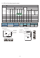
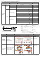
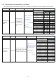
RB Unit Check contents
Ref. circuit name: _________________, Ref. address :__(00
99)
Model Name
Outlook
RB unit Add. set by Rotary-SW
Related
Indoor
Unit
Address
No. of connected IU vs. total capacity
Transmission & Power
line wiring connection
terminal
(Loose / Tilting )
Access hole for
maintenance
( Have / Not have )
Refrigerant piping
insulation
Ref. Add.
(REF AD x
10
)
Ref. Add.
(REF AD x
1
)
RB Add.
(IU AD x
10
)
RB Add.
(IU AD x
1
)
For single type
RB unit
For multi type RB unit
(single / series connection)
Number of
Connected IUs
Total capacity
(kW) of the
connected IUs
Number of
Connected IUs
Total capacity
(kW) of
the connected IUs
RB Add.
Ref. Add.
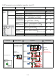
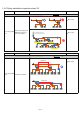
RB unit (single type) Indoor units / Branch Total capacity
UTP- RU01AH Maximum 3 units 8.0 kW or less
UTP- RU01BH
Maximum 8 units
18.0 kW or less
UTP- RU01CH 28.0 kW or less
RB unit
(multi type)
Number of
RB units
Indoor unit
/ Branch
Capacity
Each Branch Total
UTP-RU04BH
1 unit
Maximum
8 units
Up to 18.0kW Up to 56.0kW
2 units series
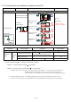
1-2-4 RB unit field setting Inspection sheet
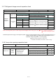
PC board (Upper side)
DIP switch
SET1
Error indicator
lamp (Red)
Power indicator
lamp (Green)
Rotary switch
DIP switch
SET2
× 10
REF × 1
× 10
RB × 1
Single type RB unit
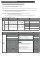
DIP switch
SET1
DIP switch
SET2
× 10
REF × 1
× 10
RB × 1
Multi type RB unit
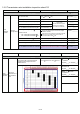
PC board (Upper side)
SV connector
SV connector
Error indicator
lamp (Red)
Power indicator
lamp (Green)