
Service Manual
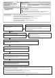
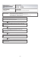

Inverter PCB short interruption
Error
OK
OK
OK
OK
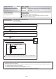
Inverter PCB
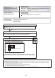
Check Point 1 : Noise, momentary power failure, voltage drop
Check if temporary voltage drop was not generated.
Check if momentary power failure was not generated.
Check if ground is connection correctly or there are no related cables near the power line.
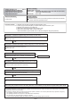
Check Point 2 : Check the magnetic contactor (for Inverter) coil side wiring
Connector and wiring connection state check
Cable open check
Cable open check
Check Point 3 : Check the wiring
(Power supply to Filter PCB (INV) to Inverter PCB)
Connector and wiring connection state check
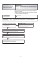
Check Point 4 : Check Main PCB
Chack Main PCB. (Refer to "Sarvise Parts Information 3, 4")
Check Point 5 : Replace Inverter PCB
Replace Inverter PCB.
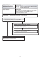
1. Noise, momentary power failure, voltage drop
2. Magnetic Relay (for Inverter) coil side wiring disconnection, open
3. Power supply to Filter PCB (INV) to Inverter PCB wiring disconnection, open
4. Main PCB defective 5. Inverter PCB defective
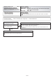
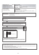
''Short interruption" received from Inverter PCB
Indoor Unit : No Display
Outdoor Unit : E. 6 7. 2
Error Code : No display
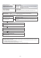
Trouble shooting 32 E67. 2
Indicate or Display:
Detective Actuators:
Detective details:
OUTDOOR UNIT Error Method:
Forecast of Cause :
04-41