
Service Manual


SERVICE PARTS INFORMATION 26
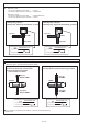
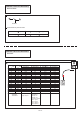
RB Unit Solenoid Valve
(SV1, SV2, SV3, SV4, SV5, SV6)
Check Point 1 : Check Solenoid Coil
Remove connector and check if coil is open.
>> If Resistance value is abnormal, replace Solenoid Coil.
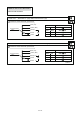
Solenoid Coil Resistance value
SV1,SV2,SV3,SV4,SV5,SV6 1.35K + 7%
-
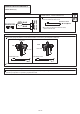
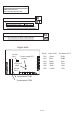
Check Point 2: Check Voltage from Main PCB
Remove connector and check the voltage (AC208- 230V).
>> If the voltage does not appear, replace Main PCB.
AC
-Upper side-
SV No. Color of CN SV Name on ST
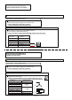
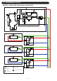
DIP SW
SET 1
Transmission PCB2
Transmission PCB1
Power supply LED
(Green)
Error LED
(Red)
DIP SW
SET 2
SV1 Green SVD1
SV2 Blue SVB2
SV3 Black SVS
SV4 White SVS
SV5 Red SVS
SV6 Yellow SVS
04-118