
Service Manual

6.DISASSEMBLY/ASSEMBLYPROCESS
CAUTION
Before servicing the unit, turn the power supply switch OFF,
When you approach PWB, be sure to equip with the electrostatic removal band.
(PWB maybe broken by static electricity.)
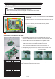
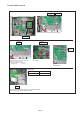
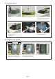
1. Indoor unit Transmisson PCB removal
06-01
1. Disconnect the connector of transmisson wire form the Terminal -
board side.
2. Hold the PCB's both end of touchable area mentioned on the left
figure.
3. Pull up the PCB one side and another side step by step.
(Do not deform the pins on the controller PCB)
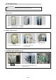
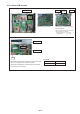
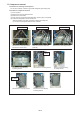
1.Before installing transmission PCB on to the Main PCB, confirm the
connector of transmisson wire was connected on the Transmission PCB.
2. Hold the PCB's both end of touchable area and adjust the position
of transmission PCB based on the position of spacers on the Main
PCB. ( Do not attach the transmission PCB wrong position.)
*When the connection of transmission PCB and the Main PCB was
wrong, the both of PCB might be broken after power supply on.
3. After adjusting the position of PCB, attach the PCB to the Main PCB.
Correct position
Incorrect position
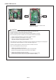
2. Indoor unit Transmisson PCB install
SET1-1 SET1-2 SET1-3 SET1-4 SET2-1 Indoor unit capacity
OFF OFF OFF OFF OFF 2.2kW
ON OFF OFF OFF OFF 2.8kW
OFF ON OFF OFF OFF 3.6kW
ON ON OFF OFF OFF 4.0kW
OFF OFF ON OFF OFF 4.5kW
ON OFF ON OFF OFF 5.6kW
OFF ON ON OFF OFF 7.1kW
ON ON ON OFF OFF 8.0kW
OFF OFF OFF ON OFF 9.0kW
ON OFF OFF ON OFF 11.2kW
OFF ON OFF ON OFF 12.5kW
ON ON OFF ON OFF 14.0kW
OFF OFF ON ON OFF 18.0kW
ON OFF ON ON OFF
22.4kW
OFF ON ON ON OFF 25.0kW
ON ON ON ON OFF
: Touchable area
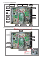
When you need to replace the transmission PCB to new one, set the DIP-SW
setting as same as the previous PCB's setting.
Spacer
6.1 Indoor Unit
28.0kW