
Service Manual
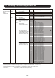
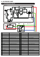


1-7 Field Setting / Function Setting for Indoor unit
Indoor unitfield setting
setting by
remote controller
Setting Mode
ITEM
CODE No.
ITEM
CODE No.
Setting Function DefaultClassification
01Address Indoor unit address 00~63 00~63
02
Refrigerant circuit address 00~99 00~99
11
Filter indicator Interval
00
01
Default
Longer
02 Shorter
Filter
13
Filter sign display 00 Enable
01 Disable
02 Display only on central remote control
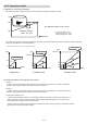
Airflow 20
Ceiling airflow
00 Default
01 High ceiling
23
Vertical airflow direction 00 Default
01 Raise
24
Horizontal swing airflow direction 00 Default
01 Left half
02
Right half
26
*1
00
01
02
03
04
05
06
07
08
09
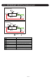
31
Static Pressure setting
- Slim Duct type -
The Range of static pressure is
different from one model to other.
SP mode 00 [ 0 in.WG ( 0 Pa) ]
SP mode 01 [ 0.04 in.WG (10 Pa) ]
SP mode 02 [ 0.08 in.WG (20 Pa) ]
SP mode 03 [ 0.12 in.WG (30 Pa) ]
SP mode 04 [ 0.16 in.WG (40 Pa) ]
SP mode 05 [ 0.20 in.WG (50 Pa) ]
SP mode 06 [ 0.24 in.WG (60 Pa) ]
SP mode 07 [ 0.28 in.WG (70 Pa) ]
SP mode 08 [ 0.32 in.WG (80 Pa) ]
SP mode 09 [ 0.36 in.WG (90 Pa) ]
Normal SP [ 0.10 in.WG (25 Pa) ]
00
01
02
03
04
05
06
07
08
09
10
11
12
13
14
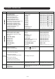
31
SP mode 00 [ 0 in.WG ( 0 Pa) ]
SP mode 01 [ 0.04 in.WG (10 Pa) ]
SP mode 02 [ 0.08 in.WG ( 20 Pa) ]
SP mode 03 [ 0.12 in.WG ( 30 Pa) ]
SP mode 04 [ 0.16 in.WG ( 40 Pa) ]
SP mode 05 [ 0.20 in.WG ( 50 Pa) ]
SP mode 06 [ 0.24 in.WG ( 60 Pa) ]
SP mode 07 [ 0.28 in.WG ( 70 Pa) ]
SP mode 08 [ 0.32 in.WG ( 80 Pa) ]
SP mode 09 [ 0.36 in.WG ( 90 Pa) ]
SP mode 10 [ 0.40 in.WG ( 100 Pa) ]
SP mode 11 [ 0.44 in.WG ( 110 Pa) ]
SP mode 12 [ 0.48 in.WG ( 120 Pa) ]
SP mode 13 [ 0.52 in.WG ( 130 Pa) ]
SP mode 14 [ 0.56 in.WG ( 140 Pa) ]
Normal SP [ 0.16 in.WG ( 40 Pa) ]
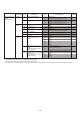
Static Pressure setting *2*3
- Duct (middle pressure) type -
The Range of static pressure is
different from one model to other.
Static Pressure setting *4*5
- Duct (high pressure) type -
The Range of static pressure is
different from one model to other.
04
05
06
07
08
09
10
11
12
13
14
31
SP mode 04 [ 0.16 in.WG ( 40 Pa) ]
SP mode 05 [ 0.20 in.WG ( 50 Pa) ]
SP mode 06 [ 0.24 in.WG ( 60 Pa) ]
SP mode 07 [ 0.28 in.WG ( 70 Pa) ]
SP mode 08 [ 0.32 in.WG ( 80 Pa) ]
SP mode 09 [ 0.36 in.WG ( 90 Pa) ]
SP mode 10 [ 0.40 in.WG ( 100 Pa) ]
SP mode 11 [ 0.44 in.WG ( 110 Pa) ]
SP mode 12 [ 0.48 in.WG ( 120 Pa) ]
SP mode 13
[ 0.52 in.WG ( 130 Pa) ]
SP mode 14
[ 0.56 in.WG ( 140 Pa) ]
Normal SP [ 0.60 in.WG ( 150 Pa) ]
30
SP mode 30
[ 1.20 in.WG ( 300 Pa) ]
15
16
17
18
19
20
21
22
23
24
25
SP mode 15
[ 0.60 in.WG ( 150 Pa) ]
SP mode 16
[ 0.64 in.WG ( 160 Pa) ]
SP mode 17
[ 0.68 in.WG ( 170 Pa) ]
SP mode 18
[ 0.72 in.WG ( 180 Pa) ]
SP mode 19
[ 0.76 in.WG ( 190 Pa) ]
SP mode 20
[ 0.80 in.WG ( 200 Pa) ]
SP mode 21
[ 0.84 in.WG ( 210 Pa) ]
SP mode 22
[ 0.88 in.WG ( 220 Pa) ]
SP mode 23
[ 0.92 in.WG ( 230 Pa) ]
SP mode 24
[ 0.96 in.WG ( 240 Pa) ]
SP mode 25
[ 1.00 in.WG ( 250 Pa) ]
26
27
28
29
SP mode 26
[ 1.04 in.WG ( 260 Pa) ]
SP mode 27
[ 1.08 in.WG ( 270 Pa) ]
SP mode 28
[ 1.12 in.WG ( 280 Pa) ]
SP mode 29
[ 1.16 in.WG ( 290 Pa) ]
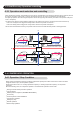
*5: ARUH72TLAV : 04 (SP mode 04) - 27 (SP mode 27) and 31 (Normal SP)
ARUH96TLAV , ARUH72TLAV1 : 05 (SP mode 05) - 30 (SP mode 30) and 31 (Normal SP)
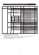
00
00
*1: Please refer to FAN PERFORMANCE CURVE within Design and Technical manual for the features of each setting.
*4: If the Setting Number in ARUH96TLAV is configured to “30”, the operation is the same as that in “29 (SP mode 29)”.
*2: If the Setting Number in ARUM30TLAV is configured to “12 to 14”, the operation is the same as that in “11 (SP mode 11)”.
*3: If the Setting Number in ARUM36TLAV is configured to “10 to 14”, the operation is the same as that in “09 (SP mode 09)”.
(Cassette type only)
(Cassette type only)
models)
(For horizontal swing equipped
01-25