
Service Manual


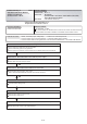

OUTDOOR UNIT Error Method ::
Outdoor Unit Network
Communication 2 Error
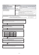
OK
Communication PCB connection check
Communication PCB check
OK
Communication line connection, open check
OK
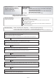
OK
OK
Outdoor unit Main PCB
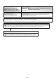
Check Point 1 : Noise, momentary open, voltage drop
Check if temporary voltage drop was not generated.
Check if momentary open was not generated.
Check if ground is connection correctly or there are no related cables near the power line.
Check Point 2 : Check the indoor unit or RB unit power supply
Main power ON check
Power cable connection and open check
Check Point 3 : Check the communication line connection
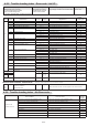
Detective Actuators:
Forecast of Cause :
No communication for 180 seconds or more from an indoor unit which
received communication once.
No communication for 180 seconds or more from all indoor units that once
received communication.
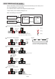
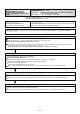
Check Point 4 : Check the Terminal resistor setting
Terminal resistor setting check
Check Point 6 : Replace Main PCB (outdoor unit/ indoor unit/ RB unit)
Check Point 5 : Check the communication PCB (outdoor unit/ indoor unit/ RB unit)
Change Main PCB and set up the original address.
Detective details:
1. Noise, momentary open, voltage drop 2. Indoor unit or RB unit power off
3. Communication line connection defective 4. Terminal resistor setting mistake
5. Communication PCB mounting defective, Communication PCB defective 6. Control PCB defective
Indoor Unit : Operation LED 9 times Flash, Timer LED 15 Times Flash,
Filter LED Continuous Flash. /
Operation LED 1 times Flash, Timer LED 4 Times Flash,
Filter LED Continuous Flash. *
Outdoor Unit : E. 1 4. 2
Error Code : 9 U / 1 4 / 1 6 / 1 4. 1 / 1 4. 2 / 1 4. 3 *
Trouble shooting 6 E14. 2
Indicate or Display:
[DIP-SW SET4-1 : ON] (Factory setting)
[DIP-SW SET4-1 : OFF]
Refer to SERVICE INFORMATION Network communication Abnormal
* Indoor unit indicates 9 U or 1 4
Peripheral device indicates 1 4 or 1 6
04-15