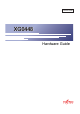
XG0448 Hardware Guide Introductory TA41001-6349 XG0448 Hardware Guide
XG0448 Hardware Guide Preface You have purchased the XG0448, a compact, 48 port 1 Gigabit Ethernet layer 2 switch that achieves unsurpassed standards of high throughput and low-latency performance. This manual explains the procedures required to install your XG0448 and should be read and understood before you start using your XG0448. First edition: June 2009 Second edition: November 2009 This manual contains the technology regulated by "Foreign Exchange and Foreign Trade Control Law.
XG0448 Hardware Guide LICENSE AGREEMENT Product Name XG Series Basic Software Total number of licenses 1 Thank you for purchasing the XG Series switch product ("Hardware") and accompanying software ("Software," together with Hardware, collectively, referred to as "Product") manufactured by Fujitsu Limited ("Fujitsu"). The use of the Product is subject to Customer's acceptance of the terms and conditions of the following requirements ("Use Requirements").
XG0448 Hardware Guide c. if in Fujitsu's sole judgment it is not commercially reasonable to perform either of the above options, subject to the limitation of liability set forth in subsection (2) above, Fujitsu shall pay for any damages Customer has incurred due to nonuse of the Software.
XG0448 Hardware Guide Contents Contents Preface ................................................................................................................................................................2 LICENSE AGREEMENT ..................................................................................................................................3 Organization and Usage of This Manual ............................................................................................................
XG0448 Hardware Guide 2.3.4 2.3.5 2.4 2.5 2.6 Contents Connecting Twisted Pair Cable / SFP+ Module / CX4 Cable ................................................................. 39 Plugging in the USB Memory .................................................................................................................. 41 Connecting a Setup PC ..........................................................................................................................42 Time Setting ......................
XG0448 Hardware Guide Organization and Usage of This Manual This manual explains what you need to know before using this device. In addition, the README file on CD-ROM contains important information. You will also need to read the file. About This Manual This manual contains important information required to use this device safely. Read this manual thoroughly before using this device.
XG0448 Hardware Guide Trademark Notification in This Manual Microsoft, MS-DOS, Windows, Windows NT, Windows Server and Windows Vista are registered trademarks of the Microsoft Corporation in the USA and other countries. Adobe and Reader are trademarks or registered trademarks of Adobe Systems Incorporated in the USA and other countries. Netscape is a trademark of Netscape Communications Corporation in the USA. UNIX is a registered trademark of Open Group in the USA and other countries.
XG0448 Hardware Guide How the Manuals for This Device Are Organized The manuals for this device are organized as follows. Use these manuals as necessary Manual Name Description Safety and Installation Guide This manual describes the safety and installation. XG0448 Hardware Guide (This manual) This manual describes the hardware of the XG0448. User’s Guide This manual describes a variety of operations and procedures, including the installation and maintenance of the XG Series.
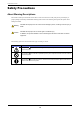
XG0448 Hardware Guide Safety Precautions About Warning Descriptions This manual contains precautions that must be taken in order to use this device safely and prevent personal injury or property damage. Please fully understand the meanings and contents of the following descriptions and symbols when reading this manual. Warning Caution Indicates that improper use can cause severe damage to person, resulting in serious injury or death. Indicates that improper use can cause light or moderate injury.
XG0448 Hardware Guide Warning Always follow the instructions for safe use of this device. Indicates that improper use can cause severe damage to person, resulting in serious injury or death. Warnings Do not disassemble, dismantle, modify or reproduce this device. Failure to follow this may result in electric shock, fire or failure. Make sure to ground. Failure to do so before use may result in electric shock. Always ground before inserting the power plug into the socket.
XG0448 Hardware Guide Caution Indicates that improper use can cause light or moderate injury. In addition, this symbol indicates a chance of damage to this device and other connected equipment. Cautions Do not touch this device for more than one minute while it is turned on. Failure to follow this may cause low-temperature burns. Avoid looking at the light source (e.g. laser light) directly. Failure to follow this may injure your eyes. Do not stand this device vertically or stack it.
XG0448 Hardware Guide Notes on Maintenance • Customers should not repair this device. In the event of failure, consult with a Fujitsu service engineer or an engineer certified by Fujitsu for maintenance. • Do not dismantle or modify this device in any manner. This device contains high voltage and high temperature parts that can be dangerous. Precautions for Use • As a guideline, the expected life of the device is approximately five years, assuming use at an ambient temperature of 25°C.
XG0448 Hardware Guide Electromagnetic Compatibility (USA) FCC Part-15 Class A Warning Note FCC WARNING: Changes or modifications not expressly approved by the party responsible for compliance could void the user's authority to operate the equipment. This equipment has been tested and found to comply with the limits for a Class A digital device, pursuant to Part 15 of the FCC Rules.
XG0448 Hardware Guide Laser Safety The XG0448 may be installed with optical transceiver modules (SFP and/or SFP+ modules), which emit invisible laser light. In the USA, these optical modules are certified as Class 1 laser products that conform to the requirements of the Department of Health and Human Services (DHHS) regulation 21 CFR, Subchapter J. This certification is indicated by a label attached to each optical module.
XG0448 Hardware Guide Notes on Use Before using this device, please read the following. • Customers are required to store and maintain configuration information for the device, after the configuration is complete. The configuration information can be used by Fujitsu or Fujitsu’s certified support engineer to restore configurations in case of failure.
Chapter 1 Getting Started This chapter lists the items that should be in the product package, and describes the names and functions of the various components. 1.1 Items in the Package, Descriptions and Functions . . . . . . . . . . . . . . . . . . . . . . . . . . . . . . . . . . . . . . . 18 1.1.1 1.2 Parts List. . . . . . . . . . . . . . . . . . . . . . . . . . . . . . . . . . . . . . . . . . . . . . . . . . . . . . . . . . . . . . . . . . . 18 1.1.2 Port Side . . . . . . . . . . . . . . . . . . . .
XG0448 Hardware Guide 1.1 Chapter 1 Getting Started Items in the Package, Descriptions and Functions Before proceeding, check all the items described below. 1.1.1 Parts List Please check that all of the following parts are included in the package. XG0448 Power Cable Console Cable Rack Mounting Brackets (Qty 2) CD-ROM Safety and Installation Guid M3 Countersunk Screws (Qty 8) XG0448 Hardware Guide (with Licence Agreement) • XG0448 The XG0448 Secure Switch.
XG0448 Hardware Guide 1.1.2 Chapter 1 Getting Started Port Side Console Port LED 10/100/1000BASE-T Ports LED USB Port SFP Slots Dump Switch Reset Switch Product Part Number, Serial Number Label • Console Port In order to set and operate the switch, use the console cable and D-SUB9pin cross cable included in this package to connect to the PC. Caution The RJ45 Console Port jack is an RS-232 serial interface. Do not plug any other interface types (Ethernet) into this jack.
XG0448 Hardware Guide Chapter 1 Getting Started LED Details Ready Error PSU Check Flash Ext.PSU SFP Link/Act SFP Link/Act/Speed Fdx • Ready LED Indicates the operational state of the switch. • Error LED Indicates a USB memory mount/access error occurred. • PSU LED Indicates the switch power supply status. • Check LED Lights orange when there is a problem. In such case, consult with the vendor's service representative immediately.
XG0448 Hardware Guide Chapter 1 Getting Started LED Functions / Behaviors LED Name Ready Error PSU Check Flash State Status Green Switch has started up correctly Green Blinking Switch is running a Power On Self Test (POST) or running from the backup firmware image (*) Off A problem has occurred Orange Indicates a compact flash mount/access error Off If a compact flash is installed, indicates no mount/access error Green PSU is operating correctly Off Power is off Orange A problem occu
XG0448 Hardware Guide 1.1.3 Chapter 1 Getting Started Power Inlet Side Expansion Slot SLOT1 • Expansion Slot Power Inlet Redundant PSU Connector MAC Address Label SLOT2 An optional expansion card can be installed in the expansion slots on the port side of the switch. Reference "1.2.3 Expansion Card" (pg.25) • Power Inlet AC power inlet for the power cable provided. • Redundant PSU Connector Connector for an external redundant power supply. Not supported.
XG0448 Hardware Guide 1.1.5 Chapter 1 Getting Started Bottom Surface Product Manufacturing Label Firmware Label • Product Manufacturing Label This indicates the model name, serial number, manufacturing date, and Class 1 Laser Product, etc. • Firmware Label This indicates the firmware version.
XG0448 Hardware Guide Chapter 1 Getting Started 1.2 Options 1.2.1 SFP Modules SFP modules (100BASE-FX/1000BASE-SX/1000BASE-LX/1000BASE-ZX/1000BASE-BX-D/1000BASE-BX-U) can be used. Precautions • Turn the switch power off to install a SFP module. • SFP modules can not be installed in the optional SFP+ extension card. • 1000BASE-BX-D and 1000BASE-BX-U SFP modules must be used in pairs • RJ45 ports 45 through 48 are 'combination' ports that are associated with the four SFP ports.
XG0448 Hardware Guide 1.2.3 Chapter 1 Getting Started Expansion Card The following describes the available expansion card options. The optional expansion card is installed in the expansion slot on the port side of the switch. The following details the functions/behaviors of each type of expansion card. SFP+ Expansion Card SFP+ Link/Act LEDs SFP+ Slots • SFP+ Link/Act LEDs Indicated the link status/communication status of the SFP+ port.
XG0448 Hardware Guide Chapter 1 Getting Started CX4 Expansion Card CX4 Link/Act LEDs CX4 Ports • CX4 Link/Act LEDs Indicates CX4 port link status / communication status. • CX4 Ports Connect to 10G Ethernet NW equipment using CX4 cable. LED Display Content LED Name CX4 Link/Act Reference State Green Status Link is established with CX4 Green Blinking 10G CX4 data traffic activity Off Link is not established "2.2.2 Installation of Extension Card" (pg.
Chapter 2 Installation This chapter describes how to install the switch and connect it to Console PC. 2.1 2.2 2.3 Requirements for Installation Environment . . . . . . . . . . . . . . . . . . . . . . . . . . . . . . . . . . . . . . . . . . . . . 28 2.1.1 Installation Requirements . . . . . . . . . . . . . . . . . . . . . . . . . . . . . . . . . . . . . . . . . . . . . . . . . . . . . 28 2.1.2 Space Requirements . . . . . . . . . . . . . . . . . . . . . . . . . . . . . . . . . . . . . . . . . . . . .
XG0448 Hardware Guide 2.1 Chapter 2 Installation Requirements for Installation Environment Before installing the switch, please check the following: • Make sure that the switch and all the other options shown in this document are available for installation. • All the cables comply with the specifications of the interface connectors. Warning Do not connect cables to interface connectors other than those adaptable to the connector’s specifications. Reference "1.1.1 Parts List" (pg.
XG0448 Hardware Guide Chapter 2 Installation Installation Condition Check List Check the following items. Check Item Check Result Nothing is put on the switch. Vents are not obstructed. The switch is not located on the table or not stuck on another switch. The switch is not located under direct sunshine, near heating appliance, under high humidity or in a dusty area. The switch is not located on unstable places where vibrating, or tilting.
XG0448 Hardware Guide 2.1.2 Chapter 2 Installation Space Requirements When installing the switch and providing maintenance, ensure the space below is maintained. Ensuring the Space for Installation (Maintenance) of the Switch When installing the switch and providing maintenance, ensure the space below is maintained. Internal cooling fans of the switch allow the air intake from the left hand side and exhaust at the right hand side.
XG0448 Hardware Guide 2.2 Chapter 2 Installation Installation This section describes how to install the switch. 2.2.1 Installation of the Switch The following describes how to install. Installation on 19” Rack The switch can be installed and operated in the EIA standard 19” rack. Prepare the following rack mounting components attached. • Rack Mounting Brackets (Qty 2) • M3 Countersunk Screws (Qty 8) Reference "1.1.1 Parts List" (pg.
XG0448 Hardware Guide 2. Chapter 2 Installation Put rack mounting brackets on the switch using M3 Countersunk Screws (Qty 8). Two ways below are possible for putting on rack mounting brackets. [STANDARD] [OFFSET] M3 Countersunk Screws Rack Mounting Brackets M3 Countersunk Screws Rack Mounting Brackets Precautions When putting on rack mounting brackets, make sure to use special screws included in the 19” rack brackets set. If other screws are used, it may break.
XG0448 Hardware Guide 2.2.2 Chapter 2 Installation Installation of Extension Card The extension cards can be installed to the switch as optional. Below describes how to install each extension card. Installation of SFP+ Extension Card /CX4 Extension Card Below describes the case of SFP+ Extension card. 1. Turn off the power of the switch. Caution Do not install/uninstall the extension cards with the power on. It may cause trouble. 2.
XG0448 Hardware Guide Chapter 2 Installation Removing SFP+ Extension Card / CX4 Extension Card 1. Turn off the power of the switch. Caution If the extension card is removed when the power is on, the Check LED will light up and the switch will go into trouble state. 2. Loosen the screws on the extension slot and remove the extension card. 3. Put the cover panel on the extension slot, and fix it on the switch with the screws.
XG0448 Hardware Guide 2.3 Chapter 2 Installation Connecting the Equipment We recommend discharging static electricity of twisted pair cable before connecting it to the switch. Also see below for how to install the USB memory. 2.3.1 Discharging Twisted Pair Cable Discharge static electricity of the twisted pair cable through the ground wire cable (ground wire for power supply, buildings, etc.) using static electricity removal tool, before connecting twisted pair cable to the switch. Precautions 2.3.
XG0448 Hardware Guide Chapter 2 Installation Cleaning of Optical Connector 1. Remove the connector guard cap of optical fiber part, and check the connector end face. If the end face is not clean, clean it with a reel type fiber cleaner. 2. Push thumb holder of a fiber cleaner and open a cap of the fiber cleaner. 3. When a cap slides and a new cleaning tape comes out, lightly apply the end face to a cleaning tape. 4. Apply the end face of the connector and rotate it (quarter turn four times). 5.
XG0448 Hardware Guide 2.3.3 Chapter 2 Installation Connecting Twisted Pair Cable / SFP Module The following describes how to connect twisted pair cable, SFP module. Use straight cable when connecting with routers and terminals. Use crossing cable in case of cascading connection with other switching HUBs with transmission mode at fixed setting other than auto negotiation. Straight cable crossing cable optical cable Management port of the switch is set auto negotiation enable by default.
XG0448 Hardware Guide Chapter 2 Installation Connecting SFP Module Firmly install SFP module to SFP slot and lock module to the switch. 100BASE-FX/ 1000BASE-SX/1000BASE-LX/ 1000BASE-ZX/1000BASE-BX-D/ 1000BASE-BX-U SFP module Caution Make sure to turn off the power when inserting and pulling out the SFP module. Precautions • RJ45 ports 45 through 48 are 'combination' ports that are associated with the four SFP ports. Their use is mutually exclusive.
XG0448 Hardware Guide 2.3.4 Chapter 2 Installation Connecting Twisted Pair Cable / SFP+ Module / CX4 Cable The following describes how to connect twisted pair cable, SFP+ module, and CX4 cable. optical cable SFP+ ports and CX4 ports are fixed at 10Gbps FULL DUPLEX MODE. Connecting SFP+ Module Firmly install SFP+ module to SFP+ slot and lock module to the switch. SFP+ Module Caution Make sure to turn off the power when inserting and pulling out the SFP+ module.
XG0448 Hardware Guide Chapter 2 Installation Precautions Cable length will be as below based on the specification of the optical fiber cable Type Core/Cladding Diameter 62.5/125µm MMF 50/125µm Minimum Transimission Band Cable Length (m) 160MHz/km 26 200MHz/km 33 400MHz/km 66 500MHz/km 82 2000MHz/km 300 Use the appropriate cable according to the installation place. Connecting CX4 Cable Firmly install CX4 cable to CX4 expansion card port and lock the cable.
XG0448 Hardware Guide 2.3.5 Chapter 2 Installation Plugging in the USB Memory USB memory can be plugged in from the interface panel of the switch. Caution Do NOT unplug out the memory stick during access. It may result in crashing setting data. Precautions It is possible to plug/unplug SFP+ module with the power on. Plug in the USB Memory Please refer to the following instructions; 1. Firmly insert the USB memory to USB port on the interface panel of the switch.
XG0448 Hardware Guide 2.4 Chapter 2 Installation Connecting a Setup PC This is to connect a set up PC to the console port of the switch using RS232C cable. Necessary Hardware / Software Please prepare the hardware & software specified below to connect to the switch. • Personal Computer 1 unit of personal computer for setting up configuration is required. • RS232C cable (Cross, D-SUB9 pin) RS232C cable is required to connect the set up PC to the switch.
XG0448 Hardware Guide Chapter 2 Installation Turn on the Power Caution • Please use the power cable included in this product. Also, please do NOT use this power cable on other products. • If the power outlet does not match with the power cord plug, please use the change plug adapter. As a safety measure to prevent electrical shocks, please make sure to connect the ground wire of the change plug.
XG0448 Hardware Guide Chapter 2 Installation Prepare a Setup PC Log on using the terminal software. 1. Start up the terminal software by using the set up PC. 2.
XG0448 Hardware Guide 2.5 Chapter 2 Installation Time Setting Make sure to set up the time before you do other settings of the switch. The time is not set at the initial timing of purchase. Please refer below command for setting up time manually using console or telnet. z Command When setting time and date to be “Jan 1, 2009 12:30:00am” type in command # date 2009/01/01.12:30:00 XG0448# configure Switch to Configuration mode. XG0448(config)# time zone -0500 When setting time zone to be “-0500“.
XG0448 Hardware Guide 2.6 Chapter 2 Installation Set up IP address Please set the IP address at times when it is required. Eg. When setting the switch through www browser or installing a firmware from the initial state of the purchase. The following commands show how to set up the IP address (ex. 192.168.1.1). z Command XG0448# configure XG0448(config)# lan 0 ip address 192.168.1.
XG0448 Hardware Guide Index Index Number M 10/100/1000BASE-T Port ........................................ 19 M3 Countersunk Screws .......................................... 18 MAC Address Label ................................................ 22 B O Bottom Surface ......................................................... 23 Options ..................................................................... 24 organization of the manuals ....................................... 9 C P CD-ROM ...........
XG0448 Hardware Guide Index U USB Memory ........................................................... 41 USB Port .................................................................. 19 W Warning Label ..........................................................
XG0448 Hardware Guide TA41001-6349 Issued on November, 2009 Issued by FUJITSU LIMITED • The contents may be revised without prior notice. • Fujitsu assumes no liability for damages to third party copyrights or other rights arising from the use of any information in this manual. • No part of this manual may be reproduced in any form without the prior written permission of Fujitsu.