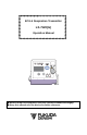
ECG & Respiration Transmitter LX-7120(G) Operation Manual ● Before using this equipment, read this operation manual thoroughly. ● Keep this manual near the device for future reference.
CAUTION Federal Law restricts this device to sale by or on the order of a physician. CAUTION Users are advised to periodically contact the FCC or specified frequency coordinator and determine if other or your transmitter frequencies that may cause interference. CAUTION The manufacturers, installers and users of Wireless Medical Telemetry System equipment are cautioned that the operation of this equipment could result in harmful interference to other nearby medical devices.
Thank you for purchasing this product. Before using this product, read this operation manual thoroughly for correct handling and operation. Safety Precautions Read the “Safety Precautions” thoroughly before use to ensure correct and safe use of the product. Make sure to follow the precautions indicated below, as these are important messages related to safety. DANGER Failure to follow this message may cause immediate threat of death or serious injury.
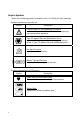
Graphic Symbols Refer to the following symbols indicated on the LX-7120(G) for their meanings. Symbols indicated on the main unit Symbol Description Caution: Refer To Accompanying Documents Indicates the need to refer to the related accompanying documents before operation. Type CF Applied Part with Defibrillation-Proof Indicates that the degree of protection against electric shock is Type CF Applied Part with defibrillation-proof. No Alarm Function Indicates no alarm function.
Precautions for Safe Operation of Medical Electrical Equipment Cautions described here are regarding the general instructions for safety use to the patient and users. As for cautions about the LX-7120(G), please refer to the following pages. CAUTION 1. 2. 3. 4. Users should have a thorough knowledge of the operation before using this equipment. Pay attention to the following when installing or storing the equipment.
CAUTION 5. 6. 7. 8. 9. After using the equipment, verify the following items. Make sure to turn off the power of the equipment. When unplugging the cables, do not apply excessive force on the cable and pull from its connector. Clean the accessories and cables, and keep them together in one place. Keep the equipment clean to ensure proper operation for the next use. Make sure to remove the battery if the equipment is not used for a long time.
Precautions about Magnetic Resonance Imaging (MRI) WARNING Do not operate this equipment in magnetic resonance imaging (MRI) environments. When conducting MRI test, remove the electrodes and sensors connected to the patient (test subject). The local heating caused by the induced electromotive force may cause burn injury to the patient (subject). For details, refer to the operation manual for the MRI testing device.
Precautions about the Pacemaker WARNING Minute ventilation rate-adaptive implantable pacemakers can occasionally interact with certain cardiac monitoring and diagnostic equipment, causing the pacemakers to pace at their maximum programmed rate. The cardiac monitoring and diagnostic equipment may possibly send wrong information. If such event occurs, disconnect the cardiac monitoring and diagnostic equipment, or follow the procedures described in the operation manual of the pacemaker.
Precautions about Waterproof CAUTION Replace the “Battery Compartment Lid” of the LX-7120(G) regularly to keep the performance of waterproof. If not regularly replaced, the quality of the lid will deteriorate and cannot keep the waterproof performance. For details about the regular replacement, contact your local Fukuda Denshi service representative. The lid may be damaged from high impact. If the LX-7120(G) is dropped or is subjected to a high impact, make sure that the lid is not damaged.
Precautions about Accessories and Optional Accessories WARNING Use only the accessories, such as ECG Lead cable, specified by Fukuda Denshi for the LX-7120(G). Otherwise, the LX-7120(G) cannot deliver its maximum performance and may be damaged, resulting in a safety hazard. CAUTION Do not reuse disposable products. Store the disposable products properly as mentioned in their user manuals. Precautions about Battery WARNING Use new "AA" size (“LR06” size) alkaline cell.
Precautions for Use of Medical Telemeter WARNING The LX-7120(G) transmitter must not be co-located or operated in conjunction with any other antenna or transmitter. This equipment complies with FCC/IC radiation exposure limits set forth for an uncontrolled environment and meets the FCC radio frequency (RF) Exposure Guidelines and RSS-102 of the IC radio frequency (RF) Exposure rules.
CAUTION And when using telemetry, which requires zone location, the Institution should nominate a person (hereinafter referred to as the “Zone Manager”) to manage the wireless channels in each zone. However, when using such telemetry in a local Institution, one person can perform both functions. The Overall Manager and Zone Manager must be selected from people who understand the characteristics and functionality of telemetry systems, and are skilled in operating telemetry.
Electromagnetic Compatibility The performance of this equipment under electromagnetic environment complies with IEC 60601-1-2 (2007). Precautions for Safe Operation under Electromagnetic Influence CAUTION If any sorts of electromagnetic wave, magnetic field, or static electricity exist around the equipment, noise interference or malfunction of the equipment may occur. If any unintended malfunction or noise occurs during monitoring, check the magnetic influence and take appropriate countermeasures.
EMC Guidance This equipment complies with IEC 60601-1-2 (2007). However, if portable transmitter or wireless LAN equipment is used extremely nearby, the electromagnetic influence may largely exceed the compliance level and may cause unexpected phenomenon such as noise interference on the waveform, etc. Therefore, this equipment should be used in a location specified by each medical institution.
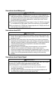
●Compliance to the Electromagnetic Immunity (1) The LX-7120(G) is intended for use in the electromagnetic environment specified below. The customer or the user of the LX-7120(G) should assure that it is used in such an environment. Immunity Test Electrostatic Discharge (ESD) IEC 61000-4-2 Electrical fast transient/burst IEC 61000-4-4 Surge IEC 61000-4-5 Voltage dips, short interruptions and voltage variations on power supply input lines.
●Compliance to the Electromagnetic Immunity (2) The LX-7120(G) is intended for use in the electromagnetic environment specified below. The customer or the user of the LX-7120(G) should assure that it is used in such an environment.
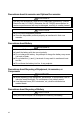
●Recommended Separation Distances between Portable and Mobile RF Communications Equipment and the LX-7120(G) The LX-7120(G) is intended for use in an environment in which radiated RF disturbances are controlled.
Blank Page xvi
CONTENTS Safety Precautions ..................................................................................... i Precaution from Fukuda Denshi....................................................... i Graphic Symbols..............................................................................ii Precautions for Safe Operation of Medical Electrical Equipment .... iii Non-Explosion Proof .......................................................................
8. Other Setting Items ............................................................................ 31 ■ Changing the Time Constant ................................................... 32 ■ Changing the Detection Sensitivity of the Pacemaker Pulse ... 33 ■ Changing the Respiration Detection Signal ON/OFF ............... 34 ■ Changing the LCD Contrast..................................................... 34 9. Changing the Transmitter Channel and Group ID ..............................
1. General Description The LX-7120(G) is a radio telemetry transmitter designed to measure the ECG and respiration waveform with one (1) “AA” size (“LR06” size) alkaline battery. Information such as ECG measurements, respiration waveform, battery level, and the conditions of the ECG electrodes are displayed on the LCD of the front panel. ECG lead selection is available using the two buttons (Enter and ▽) on the front panel.
1.
2. Names of Parts and Their Functions Channel Number Label Indicates transmitter channel number. LCD Displays measurement waveform and transmitter information. Neck Strap Hole Attaches the neck strap. ECG/RESP Input Connector Connects the ECG lead cable to measure ECG and respiration waveform. Enter button Uses for setup. Refer to “Safety Precautions” in this manual’s preface. ▽ button Uses for setup. EVENT Button Activates the function assigned on the receiving monitor.
2. Names of Parts and Their Functions Refer to “Safety Precautions” in this manual’s preface.
3. Preparation 1) Installing the Battery The LX-7120(G) functions with one (1) "AA" size (“LR06” size) alkaline battery. With new battery, the LX-7120(G) is capable of approximately 3 days continuous operation. WARNING Unplug the ECG lead cable when the battery compartment lid is opened. Otherwise, patient leakage current beyond the allowable value may occur. Use new "AA" size (“LR06” size) alkaline battery. Do not short out the (+) and (-) terminals.
3. Preparation Lift the lock lever to open the battery compartment lid as shown in the left picture. Install new battery according to the polarity indication inside the battery compartment. Make sure to first Insert the battery into the battery compartment from the minus (-) terminal as shown in the left picture. Hook the lock lever on the projection from the body and press it down until it is horizontal (flat position).
3. Preparation 2) Operating Power Switch Turning the power switch to “ON” Rotate the power switch to the left until it clicks. LCD screen turns ON and measurement starts. Regarding the LCD screen, refer to page 17 (6. Measurement). The screen automatically turns itself OFF after a minute. After the power is turned ON, make sure to check the remaining battery level on the LCD screen. Refer to the following symbol about the remaining battery level.
3.
4. ECG Monitoring ■ Connecting the ECG Lead Cable and Electrodes The optional ECG lead cables for LX-7120(G) are as follows. ECG Lead Cables AHA color code: Item No. Applicable Lead CMT-01HTH-0.8DA Limb Lead (1CH) CMT-02HTH-0.8DA Limb Lead (2CH) CMT-03HTH-0.8DA Limb Lead (1CH) +Chest (1CH) CMT-01FTH-0.8DA Limb Lead (1CH) CMT-02FTH-0.8DA Limb Lead (2CH) CMT-03FTH-0.
4. ECG Monitoring The relations between the attached electrode positions and lead method are as follows. Attach the electrodes to monitor proper waveform. For 3-electrode lead cable For AHA color code electrode position (No. CMT-01HTH-0.8DA, CMT-01FTH-0.8DA) White (RA) Black (LA) Red (LL) Standard Limb leads Standard Limb leads can be selected from lead I, lead II, or lead III under the setting of the equipment. Refer to “7.
4. ECG Monitoring For 5-electrode (Chest) lead cable For AHA color code electrode position (No. CMT-03HTH-0.8DA, CMT-03FTH0.8DA) White (RA) Black (LA) Brown (V) Green (RL) Red (LL) Standard Limb lead and Chest lead One limb lead and one chest lead (Brown) measurements are available. Standard Limb leads can be selected from lead I, lead II, or lead III under the setting of the equipment. The chest lead waveform is measured from the chest lead (Brown) positioned on the chest. Refer to “7.
4. ECG Monitoring ■ Attaching the Electrodes CAUTION Always use the same type of electrodes. If different types of electrodes are used at the same time, the difference between the polarization potential from each electrode may interfere with monitoring. Do not reuse the disposable electrodes. It is intended for single patent use only. Clean the electrode sites with alcohol wipes or other skin preparation. If necessary, shave the electrode sites to remove excessive hair.
4. ECG Monitoring ■ Connecting the ECG Lead Cable to the LX-7120(G) Insert the ECG lead cable firmly into the ECG/RESP input connector matching the transmitter’s connector guide and the direction of the notched part on the connector.
4. ECG Monitoring CAUTION There are some cases when pacemaker pulse cannot be detected depending on the pacemaker type, pulse voltage, pulse width, electrode lead type (unipolar, bipolar), electrode placement, or lead method which causes the pacemaker pulse amplitude to decrease and disables pacemaker pulse detection. If signals similar to a pacemaker pulse are present, such as electric blanket noise or excessive AC frequency noise, these may be erroneously detected and displayed as a pacemaker pulse.
5. Respiration Monitoring Follow the preparation of “4.ECG Monitoring” to allow the respiration monitoring. This respiration monitoring is performed with impedance method. The ECG electrodes are also used for detecting the respiration. Each lead cable specifies the electrodes to detect the respiration. For 3-electrode and 5electrode (chest) lead cable, the electrodes to detect the respiration are fixed as follows. Even if lead method is switched, they are no changes.
5.
6. Measurement Turn ON the power and the measurement starts. ■ Starting Screen When the power is turned ON, the channel number configured on the LX7120(G) is displayed at the top of the LCD. Make sure whether the channel number on the LCD matches the channel number indicated on the label of the LX-7120(G) and the channel number configured on the receiving monitor. This screen automatically moves onto the next waveform display screen.
6. Measurement ■ Waveform Display ●ECG Display Screen (1) ECG1 waveform, heart rate, pacemaker marker, remaining battery level, and electrode check message are displayed. The LCD display will automatically turn itself OFF after 60 seconds if no operation is done. To restart the LCD display, refer to page 29. When the LCD display is active, press the ▽ button to move onto the next waveform display screen. 【Descriptions of the Screen】 The descriptions of contents displayed on the LCD are as follows.
6. Measurement Displays the detection marker when the pacemaker pulse is detected. Indicates the measuring lead. Indicates the ECG waveform size displayed on the LCD. CAUTION The ECG waveform size setting displayed on the LCD does not interact with the one displayed on the screen of the receiving monitor, because the LX-7120(G) cannot transmit the setting information of the waveform size to the receiving monitor.
6. Measurement ●ECG Display Screen (2) ECG2 waveform, heart rate, pacemaker marker, remaining battery level, and electrode check message are displayed. NOTE If a 3-electrode lead cable is used, this screen will not appear. The LCD display will automatically turn itself OFF after 60 seconds if no operation is done. To restart the LCD display, refer to page 29. When the LCD display is active, press the ▽ button to move onto the next waveform display screen.
6. Measurement Displays the detection marker when the pacemaker pulse is detected. Indicates the measuring lead. Indicates the ECG waveform size displayed on the LCD. CAUTION The ECG waveform size setting displayed on the LCD of the LX7120(G) does not interact with the one displayed on the screen of the receiving monitor, because the LX-7120(G) cannot transmit the setting information of the waveform size to the receiving monitor.
6. Measurement ●Respiration Display Screen Respiration waveform, respiration rate, remaining battery level, and electrode check message are displayed. The LCD display will automatically turn itself OFF after 60 seconds if no operation is done. To restart the LCD display, refer to page 29. When the LCD display is active, press the ▽ button to move onto the next waveform display screen. 【Descriptions of the Screen】 The descriptions of contents displayed on the LCD are as follows.
6. Measurement CAUTION The respiration waveform size setting displayed on the LCD does not interact with the one displayed on the screen of the receiving monitor, because the LX-7120(G) cannot transmit the setting information of the waveform size to the receiving monitor. If the respiration waveform size displayed on the screen of the receiving monitor is changed, follow the instruction in the operation manual of the receiving monitor.
6.
7. Operation ■ Changing Setup ●ECG Display Screen (1) In the ECG display screen (1), the ECG waveform size and lead displayed on the LCD of the LX-7120(G) can be changed. 【Setting Method】 How to enter the setup mode: Press and hold the Enter button for 2 seconds in the ECG display screen (1). <> Lead of ECG 1 can be switched when 3-electrode lead cable or 5-electrode (Chest) lead cable is used. Select an appropriate lead by checking the ECG waveform on the LCD.
7. Operation << Returning to ECG Display Screen (1) >> Press the ▽ button to highlight the Return button. Press the Enter button to return to the ECG display screen (1). CAUTION Do not operate the LX-7120(G) with the setup screen open to prevent the settings to be changed due to an unintended operation. Make sure to press the Return button to terminate the setup screen. The LCD display will automatically turn itself OFF after 60 seconds if the Return button is not pressed.
7. Operation ●ECG Display Screen (2) In the ECG display screen (2), the ECG waveform size displayed on the LCD of the LX-7120(G) can be changed. 【Setting Method】 How to enter the setup mode: Press and hold the Enter button for 2 seconds in the ECG display screen (2). << Changing ECG2 Waveform Size on LCD >> The size indication of ECG 2 is highlighted. Pressing the Enter button will sequentially change the size of ECG 2.
7. Operation ●Respiration Display Screen In the respiration display screen, the respiration waveform size displayed on the LCD of the LX-7120(G) can be changed. 【Setting Method】 How to enter the setup mode: Press and hold the Enter button for 2 seconds in the respiration display screen. << Changing Respiration Waveform Size on LCD>>> The size indication of the respiration is highlighted. Pressing the Enter button will sequentially change the size of respiration.
7. Operation CAUTION Do not operate the LX-7120(G) with the setup screen open to prevent the settings to be changed due to an unintended operation. Make sure to press the Return button to terminate the setup screen. The LCD display will automatically turn itself OFF after 60 seconds if the Return button is not pressed. ■ Restarting the LCD display The LCD display will automatically turn itself OFF after 60 seconds if no operation is done.
7.
8. Other Setting Items The following settings are available for the LX-7120(G) depending on the use and condition of the patient. For details of the settings, contact our service representative. Items Time Constant Detection Sensitivity of Pacemaker Pulse Respiration Detection Signal LCD Contrast Transmitter Channel Selection 0.4 sec., 0.1 sec. Default 0.4 sec. Backup Yes Low, Mid, High Mid Yes ON, OFF ON Yes 8 Yes 9501 Yes 00 Yes 8 steps One from the following channels.
8. Other Setting Items ■ Changing the Time Constant The default setting of the time constant is “0.4 seconds”. If a stable monitoring is difficult with excessive change in the baseline due to excessive body motion of the patient or an interference noise, such as AC frequency, by changing the time constant to “0.1 second” the monitoring may become relatively stable. For details of the setting change, contact your local Fukuda Denshi service representative. CAUTION When changing the time constant to “0.
8. Other Setting Items ■ Changing the Detection Sensitivity of the Pacemaker Pulse The default setting of pacemaker pulse detection sensitivity is “Mid”. The “Mid” setting can detect and reject the following pacemaker pulse specified in ANSI/AAMI EC13 standard. Detection/ Rejection of Pacemaker Pulse: a) Pacemaker Pulse without Over/Undershoot: Capable to reject pulses of pulse width 0.1 to 2ms, amplitude ±2 to ±700mV b) Pacemaker Pulse with Over/Undershoot: Rejection is not possible.
8. Other Setting Items ■ Changing the Respiration Detection Signal ON/OFF The default setting of the respiration detection signal is “ON”. The respiration waveform can be detected when the setting of the respiration detection signal is turned “ON”. WARNING If the LX-7120(G) is used with minute ventilation rate-adaptive implantable pacemaker, the respiration detection signal may cause the pacemaker to pace at its maximum programmed rate.
8.
9. Changing the Transmitter Channel and Group ID ■ Changing the Transmitter Channel The LX-7120(G) is a transmitter of PLL synthesizer type, and its transmitter channel can be programmed. It can be set up with an arbitrary channel among the channels assigned by the Telemetry Laws (according to each country). For details of the setting change, contact your local Fukuda Denshi service representative.
11.
10. Troubleshooting ■ List of Displayed messages Transmitter (main unit) Message Cause Failed to transmit waveform and value. Solution Contact your local Fukuda Denshi service representative. Faulty EEPROM. Failed to initialize CPU. ECG Message Cause Electrode is off. Solution Check the electrode condition. Character string displayed, such as LA, depends on the detached electrode position.
10. Troubleshooting ■ Troubleshooting Make sure of the following. However, if there is no improvement in the phenomenon, contact your local Fukuda Denshi service representative. Transmitter (main unit) Phenomenon Cause Solution Nothing is displayed No battery or wrong Install the battery correctly. on the LCD when the polarity power switch is turned Battery level is Replace the battery with a ON. empty. new one. Nothing is displayed on the receiving monitor screen.
10. Troubleshooting ECG Phenomenon Cause “ELECTRODE?” Lead cable is off. message is displayed. Solution Check the connection between the lead cable and the LX-7120(G). Check the connection between the lead cable and the electrode. Faulty Lead cable. Replace the ECG cable with a new one. Electrode is peeling Replace the electrode with a off. new one. Polarization potential of the electrode is too high. ECG waveform contains noise Respiration waveform cannot be measured.
10. Troubleshooting ■ In Case of Dropping the LX-7120(G) into Water In case of dropping the LX-7120(G) into water containing disinfectant, pick up the LX-7120(G) quickly from it. Rinse it well with running water, and dry it thoroughly with a soft cloth. CAUTION Do not use a drier. The LX-7120(G) shape may change or be broken. When the LX-7120(G) is rinsed with running water, make sure to close the battery compartment lid.
11. Cleaning and Disinfection The Cleaning and disinfection of the LX-7120(G) and ECG lead cable shall be performed as follows. CAUTION Do not sterilize the LX-7120(G) and ECG lead cable in any manners, such as radioactive rays, steam, or ethylene oxide. ■ Cleaning and Disinfecting the LX-7120(G) ●Cleaning Clean the LX-7120(G) using squeezed gauze or an absorbent cotton cloth dampened with alcohol or a neutral cleanser. CAUTION Clean the equipment frequently so stains can be removed easily.
11. Cleaning and Disinfection ■ Cleaning the ECG lead cable After using the cable, clean it with neutral detergent or 70% isopropyl alcohol. CAUTION Do not use thinner, toluene, or other organic solvents to clean the cables. Do not pull the cable and do not hold the connector part when cleaning. (It may degrade the cable coating and result in damage. Particularly organic solvents and antiseptic solution such as cresol soap solution will degrade the cable coating.
12. Maintenance and Inspection This section explains the daily checks and periodic checks of the LX-7120(G). To ensure safety, reliability, and high performance, a “Daily Check” and “Periodic Check” must be performed. We are not liable for any accident arising from lack of maintenance. CAUTION Do not open the housing or attempt service. The service should be done by Fukuda Denshi or Fukuda Denshi’s representative.
12. Maintenance and Inspection Daily Check List No. Inspected Date Inspected by Location Device Type LX-7120(G) S/No. Date of Purchase Items Appearance Battery Compartment Power Supply ECG Connectors ECG Lead cable Wireless Channel Transmission Function Display Function Periodic Check Comment 46 Details Visually check for any damage, cracks, chip, peeled label, and loosen screw on the housing. Visually check for the ring condition of the battery compartment lid.
13. Standard and Optional Accessories This section lists the accessories for the LX-7120(G). WARNING Use only the accessories, such as ECG Lead cable, specified by Fukuda Denshi for the LX-7120(G). Otherwise, the LX-7120(G) cannot deliver its maximum performance and may be damaged, resulting in a safety hazard. CAUTION For quality improvement, specifications are subject to change without prior notice. ■ Standard Accessories No.
13. Standard and Optional Accessories ■ Optional Accessories The following accessories are available as optional for the LX-7120(G). Purchase them as required. ●ECG, Impedance Respiration Measurement AHA color code: Item 48 Model Type ECG Hook Type Lead Cable CMT-01HTH-0.8DA ECG Hook Type Lead Cable CMT-02HTH-0.8DA ECG Hook Type Lead Cable CMT-03HTH-0.8DA ECG Clip Type Lead Cable CMT-01FTH-0.8DA ECG Clip Type Lead Cable CMT-02FTH-0.8DA ECG Clip Type Lead Cable CMT-03FTH-0.
14. Specification ■ Specification CAUTION For quality improvement, specifications are subject to change without prior notice. Standard Specification Size: 60.6(W) x 60.0(H) x 20.
14. Specification Time Constant: Pacemaker Pulse Detection/ Rejection: Protection to Defibrillation: 0.4 sec ±25% Switching and available to set 0.1 sec ±25% Comply with ANSI/AAMI EC13 Pacemaker pulse rejection capability Meet the requirement of IEC60601-2-27 Respiration (Impedance Method) Accuracy of Sensitivity: Resp. Display Range: Display Error of Respiration Rate: Measured Current of Respiration: 10mm/1Ω ±2mm (When standard Impedance is 480Ω.
14.
14. Specification ■ Displays The following displays are shown on the LCD of the LX-7120(G). Display Description Starting Screen Displays after turning on the power. Automatically moves onto the channel display screen. Channel Display Screen Displays the transmitter channel after turning on the power and also when refreshing the screen. Automatically move onto the waveform display screen. EVENT Displays when the EVENT button is pressed. Automatically move onto the channel display screen.
14. Specification ■ Details of the “ELECTRODE?” Message The following “ELECTRODE?” messages are displayed on the LCD depending on the selected lead cable and lead.
14. Specification ■ List of Setup Items This section lists the available selection, default setting, and backup status for each setup item, which is available for the LX-7120(G). Items ECG Lead Display Size of ECG (1) Display Size of ECG (2) Display Size of Respiration Waveform Selection I, II, III ×1, ×1/2 ×1, ×1/2 Default II ×1 ×1 Backup Yes Yes Yes ×1, ×1/2 ×1 Yes For details of the following settings, contact our service representative. Items Selection Default Backup Time Constant 0.4 sec., 0.
39-4, Hongo 3-chome, Bunkyo-ku, Tokyo, Japan Phone:+81-3-3815-2121 Fax:+81-3-3814-1222 Printed in Japan 4L0113110 201509