30" MICROWAVE OVEN TRIM KIT INSTALLATION GUIDE GUIDE D’INSTALLATION
Standard Installation Guide EN This kit is ul approved to allow certain microwave ovens to be installed above any electric wall oven. Please see the use & care manual regarding approved built-in applications. IMPORTANT This Trim Kit is designed for and approved only for Fulgor Milano Microwave Oven specifying Trim Kit F4TK30MWO.
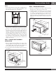
Standard Installation Guide EN STEP 2 - EXHAUST DUCT ASSEMBLY INSTALLATION 1. Place the Exhaust Duct Assembly in the center of the opening. Align the front edge of the duct with the front of the cabinet. 2. Secure the Exhaust Duct Assembly with two Screws D. See Sketch 3. Foot Exhaust duct assembly Duct recess Sketch 5 Screw D Screw D Exhaust duct assembly right side aligns to front edge of shelf 3.
Standard Installation Guide EN Flush Installation Guide 4. Back Frame Installation: Position back frame equal space top to bottom, side to side. Mark for 4 holes, center punch and pre-drill with 1⁄ 16” drill bit. Secure frame with 4 Screws (E). See Sketch 7. STEP 1 - CABINET OR WALL OPENING The opening in the wall or cabinet must be within the following dimensions: CUT OUT Mounting holes Mounting holes A 25 1⁄4” (641.4 mm) B 30 1⁄8” (765.2 mm) C 20 5⁄16” (516.
Flush Installation Guide NOTES • Please allow minimum 3" (76 mm) wood gap between the microwave oven cutout and the appliance cutout below the microwave oven. See Sketch 2. Microwave cutout Wall oven cutout EN STEP 3 - FRAME INSTALLATION 1. Place the oven adjacent to the wall or cabinet opening. Plug the power cord into the electrical outlet. 2. Carefully guide the assembled oven into the prepared opening. Slide the oven on the Exhaust Duct Assembly. See Sketch 4.
Flush Installation Guide EN 3. Disassembly: The Front Frame and Back Frame come pre-assembled with ball studs engaged in the receivers. Separate the Front Frame from the Back Frame. Place the assembly face down on a protected surface. At the location of the ball stud, insert a flat head screwdriver between the Front Frame and the Back Frame and gently pry up to disengage the ball stud from the receiver. Repeat for each corner. See Sketch 6. Sketch 8 Sketch 6 4.
YOUR LIFE | OUR PASSION www.fulgor-milano.