
Installation Manual


EN
5
Flush Installation Guide
NOTES
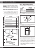
• Please allow minimum 3" (76 mm) wood gap between
the microwave oven cutout and the appliance cutout
below the microwave oven. See Sketch 2.
3"
(76 MM)
Min.
Microwave cutout
Wall oven cutout
Sketch 2
• If the dimension of DEPTH (C) is more than 21" (533.4
mm), the outlet location may be any area on the rear wall.
• The floor of the opening should be constructed of
plywood strong enough to support the weight of the oven
and floor load (about 100 pounds/45 KG). The floor
should be level and 90˚ with the face of the cabinet for
proper installation and operation of the oven. Be sure
to check the local building code as it may require that
the opening be enclosed with sides, ceiling and rear
partition. The proper functioning of the oven does not
require the enclosure.
STEP 2 - EXHAUST DUCT ASSEMBLY
INSTALLATION
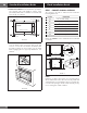
1. Place the Exhaust Duct Assembly in the center of the
opening. Align the front edge of the duct with the front
of the cabinet. Align the front edge of the right side of
the duct with the front of the shelf. See Sketch 3.
2. Secure the Exhaust Duct Assembly with two Screws D.
See Sketch 3.
Exhaust duct assembly
right side aligns to front
edge of shelf
Screw D
Screw D
Sketch 3
STEP 3 - FRAME INSTALLATION
1. Place the oven adjacent to the wall or cabinet opening.
Plug the power cord into the electrical outlet.
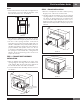
2. Carefully guide the assembled oven into the prepared
opening. Slide the oven on the Exhaust Duct Assembly.
See Sketch 4. Avoid pinching the cord between the
oven and the wall. Adjust the position of the oven so
that the feet of the oven are fitted into the recesses of the
Exhaust Duct Assembly and door will open properly. See
Sketch 5.
Screw D
Screw D
Sketch 4
Exhaust
duct
assembly
Foot
Duct recess
Sketch 5