FM4BM30FBI FM4BM30IFBI FRIDGE INSTALLATION GUIDE
TABLE OF CONTENTS PAGE 2 1. Important Instructions 1.1 Important safety instructions 1.2 Children safety 2. Technical Requirements 2.1 Appliance features requirements 2 3 3 and 3. Preparing The Installation 3.1 Transport to installation unpacking 3.2 Pre-installation 3.3 Installation Location 3.4 Preparation of Cabinetry 3.5 Ventilation 3.6 Electrical Connection 3.7 Water Connection installation 3 4 site and 4 4 4 4 4 4 5 4. Niche Dimensions 4.1 Niche Dimensions and Installation 4.
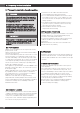
1 - Important Instructions 1.1 Important safety instructions 1.2 Children safety Symbols used in the Guide: NOTE Tips for the correct use of the appliance IMPORTANT Directions to avoid appliance damage WARNING Directions to prevent injury DANGER: Risk of child entrapment. Before you throw away your old refrigerator or freezer: • Take off the doors • Leave the shelves in place so that children may not easily climb inside.
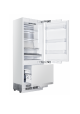
2 - Technical Requirements 2.1 Appliance features and installation requirements Appliance dimensions Overlay Built-In Series Series 30” w: 29-11/16” (754mm) h: 83-1/4” (2115mm) d: 23-5/8” (600mm) Voltage AC 110 - 120V 60Hz Power supply cable 90° Nema 5-15P Water supply pressure between 25psi to 80psi (1.7 Bar - 5.
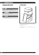
3. Preparing for the Installation 3.1 Transport to installation site and unpacking WARNING The product can present a tip hazard if not secured to adjacent cabinets or if anti tip brackets are not installed. Due to tip hazard handle with care when unpacking and transporting the unit. To avoid injury or death it is recommended that the installation and repair be conducted by a qualified contractor.
3.7 Water Connection (where applicable) • Location of the water supply (refer to niche diagram). • Water system of the refrigerator must be connected to the potable water main in the house with a valve that is accessible in an adjacent cabinet, so that it is accessible after installation. • Supplied water pressure should be between 25-80 psi (1.7-5.5 Bar) for proper function of ice maker and water dispenser. • Water pressure from RO systems are typically insufficient for proper function of the ice maker.
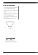
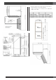
4. Niche Dimensions 4.
• Distances between the cabinet doors and the kitchen cabinet must be 1/8" (3 mm) minimum. • Height of the Kitchen Toe kick Based on the Min./Max. Height of the Cabin.
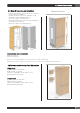
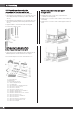
5. Unpacking 5.1 Unpacking and removing the connectors on the side wall of unit 1. Side furniture connection bracket closing parts 2. Seals between the Furniture, Door and Inner Door for the Fridge (Already attached in products with clad doors) 3. Seals between the Furniture, Door and Inner Door for the Freezer (Already attached in products with clad doors) 4. Upper furniture connection bracket closing part 5. Freezer Door upper cover 5.
6. Installation IMPORTANT The following instruction for installation apply to all models. Continue to install the product according to the instructions below. Additionally, consider national and local instructions regarding installation. Please observe the following: WARNING Always ensure the area to be drilled into is free of any waterlines or electrical circuits which could cause, damage, injury or death.
IMPORTANT If you are not comfortable the supplied connection and anti tip brackets are fit to the wall as securely as they should be, you can use alternative anti-tip methods. If there is a cabinet panel at the back wall of the refrigerator, please make sure that it is securely fixed to the wall. For this, you need to be sure that the back wall of the cabinet panel is affixed to the wall stud. 6.
7. Cabinet Installation 7.1 Removing fridge from the wooden pallet • Remove brackets which secure the fridge to pallet as shown below. • With the help of a second person carefully recline the refrigerator and remove from pallet ensuring no damage to the underside of unit. When transporting unit always carry from side to ensure feet of unit are on the fridge cart base.
7.3 Adjusting the height of the refrigerator in the niche 7.
7.6 Securing the upper bracket IMPORTANT • Attach the upper bracket to the furniture with 4 screws (Item #16). • Preparing a pilot reference hole in the side gable could make these process of afixing to side cabinet gable easier The depth of the niche must also be designed to accommodate the minimum depth requirement plus the thicker door panel if desired. Regardless of door thickness the maximum panel weights must always be respected or warranty of product will be void. 7.
8. Bottom Cabinet Installation 8.1 Complete the water connection 8.3 Attaching the lower vent hole assembly Allow sufficient slack in waterline to ensure an easy bend and clear connection with no tension or potential kinks in the supply line to the connector Use 2 screws to attach the lower vent hole part. The lower grill can be adjusted to accommodate the cabinet toe kick.
9. Hinge Adjustment and Reversing the Door Swing 9.1 Adjusting the spring tension of the hinge IMPORTANT • The door must be fully open during this adjustment. • The hinge tension adjustment must be performed only after the door panel has been adjusted. • Set the tension level of the hinge to "0”. WARNING Failure to set the hinge to "0" and continuing the installation like that may cause injury. • Use a hand tool to adjust the tension of the upper and lower hinges of the upper door.
9.2 Replacing the hinges 9.3 Installing the Upper Door • Remove the hinge pocket cover located at the other side where you will affix the hinges. • Remove the screw cover and screws securing the the hinges. • Place the upper inner door to the refrigerator using the door gasket to help hold door in place and affix it back to hinges with 4 screws • Remove the lower right hinge by loosening its 2 screws and affix it to its slot at the upper left side.
10. Overlay Panel Installation and Preparation This section contains information about preparing the cabinet doors and mounting them to the product. 10.2 Removing the overlay panel mechanism covers Maximum weights of the cabinetry to be mounted to the product are as follows. A magnet is located in the cover of the door hanger bracket.
• Remove the panel adjustment mechanism covers and panel afixing brackets from the lower part of the freezer Door. 10.4 Preparing the overlay panels NOTE IMPORTANT • Use screws suitable for the door thickness to avoid damage to the finished surface of the panel • Install the panel brackets using screws (#23). You can also use the template (#24) provided with the product to align these parts. It is recommended to keep this template for future reference.
Install the lower panel bracket using the panel screws (#23). You can also use the template (#24) provided with the product to align these parts. It is recommended to keep this template for future reference. 10.6 Installing the upper door panel • Attach the cabinet door to the fridge door Attach the three upper metal “L” brackets (#14) using 2 screws (#15) for each. Attach the door handle to the upper door panel prior to installing the panel on the fridge.
• Adjust from lower part of the door with 2 screws removed from bracket (shown below) together with 2 slotted screws. • Use the bracket(#21)to secure the upper door panel to the upper door, use 2 screws (#20) and 1 screw (#22) to fix. • Remove screws from mounting bracket to affix the upper/lower mounting bracket cover. NOTE Always keep spare parts for future use as they may be required to complete a door swing change in the future 10.
• Reinstall the main freezer bin onto the rail and secure the bin onto the rails with the provided thumb screws image #1 image #2 • If an adjustment is needed for the upper door panel please follow the illustrations below using the adjustment mechanisim 10.8 Panel Adjustments Panel-adjustment for upper door – top Panel-adjustment for upper door – bottom 1. Use the double-threaded height adjustment bolts to align the door panel 2. Adjust set screw 1 (see the graphic) to shift the panel side to side. 3.
If an adjustment is needed for the freezer door panel please follow the illustrations below using the adjustment mechanisim Panel-adjustment for freezer door panel - upper 1. Use the freezer cabinet door adjustment washer to align the door panel top part. 2. Adjust set screw 1 (see the graphic) to shift the panel side to side. 3. Select fixing hole (see the graphic) to shift the panel forward/backward; secure fixing screw to set the panel in place. Panel-adjustment for freezer door panel - upper 4.
WARRANTY for Home Appliances ENGLISH Warranty Class Description of warranty coverage Doors, handles, glass, product frames, racking, interior and exterior surfaces are covered by a limited 30-day parts-only warranty for cosmetic defects proven to have originated from the factory. It is the responsibility of the owner to inspect the product and report any such claims within this 30 day period.