
Installation Instructions


EN
6
3 - Installation Information
WARNING
• Excessive Weight Hazard
Use two or more people to move and install range.
Failure to do so can result in back or other injury.
• Cut Hazard
Beware of sharp edges. Use the polystyrene ends when
carrying the product. Failure to use caution could result in
minor injury or cuts.
Do not obstruct the flow of combustion air at the oven vent
nor around the base or beneath the lower front panel of the
range. Avoid touching the vent openings or nearby surfaces
as they may become hot while the oven is in operation. This
range requires fresh air for proper burner combustion.
NEVER cover any slots, holes or passages in the oven or
cover an entire rack with aluminum foil. Doing so blocks
air flow through the oven and may cause carbon monoxide
poisoning. Aluminum foil linings may also trap heat, causing
a fire hazard.
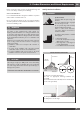
CHOOSING RANGE LOCATION
Carefully select the location where the range will be placed.
The range should be located for convenient use in the kitchen,
but away from strong drafts.
Strong drafts may be caused by open doors or windows, or by
heating and/or air conditioning vents or fans.
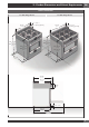
IMPORTANT NOTE
When installing against a combustible surface, a minimum
riser is required for a the range, Follow all minimum
clearances to combustible surfaces shown in the illustration
on the previous pages.
Before moving the range, protect any finished flooring and
secure oven door(s) closed to prevent damage.
Do not lift or carry the range door by the door handle.
To eliminate the risk of burns or fire by reaching over heated
surface units, cabinet storage space located above the surface
units should be avoided. If cabinet storage is to be provided,
the risk can be reduced by installing a range hood that projects
horizontally a minimum of inches beyond the bottom of the
cabinets.
All openings in the wall or floor where the range is to be
installed must be sealed.
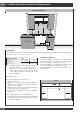
TOOLS WILL YOU NEED
006
Remove packaging materials and literature package from the
cooktop before beginning installation.
Remove Installation Instructions from the literature pack and
read them carefully before you begin
MATERIALS PROVIDED
ANTI-TIP BRACKET
BRACE ABD SCREWS
APPLIANCE
PRESSURE
REGULATOR
FLARE
UNION
ADAPTOR
GASKET
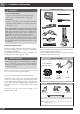
MATERIALS REQUIRED (not provided)
Shut-Off Valve
Pipe Fittings
5-foot maximum length, 5/8” O.D. CSA-approved flexible
metal gas supply (3-foot maximum length in Massachusetts only)
NOTE: Purchase new flexible line; do not use previously used
flexible gas line.
Joint Sealant