INSTALLATION AND OPERATION MANUAL Hopkins Horizontal Coil Design Thermal Fluid Heaters Serial/ National Board Number Model Fulton Order Sold To Job Name Date HPN-IOM-2014-0416
TABLE OF CONTENTS HPN-IOM-2014-0416 Introduction 1-1 FILLING PROCEDURE FOR SYSTEMS OPEN TO ATMOSPHERE ....................................................3-3 FILLING PROCEDURE FOR SYSTEMS EQUIPPED WITH INERT BLANKETS .................................3-3 Overview .............................................................................................................. 1-2 Warnings & Cautions............................................................................................
TABLE OF CONTENTS HPN-IOM-2014-0416 Safety Check Procedures ..................................................................................... 4-6 LIQUID LEVEL SWITCH ................................................................................................................4-6 STACK LIMIT .................................................................................................................................4-6 DIFFERENTIAL PRESSURE SWITCH ..................................................
INTRODUCTION INTRODUCTION INSTALLATION OPERATION MAINTENANCE WARRANTY & PARTS Questions? Call (315)298-5121, or visit us online at www.fulton.
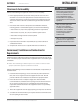
INTRODUCTION HPN-IOM-2014-0416 SECTION 3 Overview Warnings & Cautions Prior to shipment, the following inspections and tests are made to ensure the highest standards of manufacturing for our customers: WARNINGS and CAUTIONS appear in various chapters of this manual. It is critical that all personnel read and adhere to all information contained in WARNINGS and CAUTIONS. Material inspections WARNINGS must be observed to prevent serious injury or death to personnel.
INSTALLATION INTRODUCTION INSTALLATION OPERATION MAINTENANCE WARRANTY & PARTS Questions? Call (315) 298-5121, or visit us online at www.fulton.
INSTALLATION ! WARNING All information in this manual is for reference and guidance purposes, and does not substitute for required professional training, conduct, and strict adherence to applicable jurisdictional/professional codes and regulations. Unless otherwise noted, this heater is certified for indoor installation only. A competent rigger experienced in handling heavy equipment should handle rigging your equipment into position. The equipment must be installed on a non-combustible surface.
SECTION 2 INSTALLATION HPN-IOM-2014-0416 Clearances & Serviceability Adhere to the following for equipment clearances and serviceability: 1. Ensure appropriate front, back, sides and top clearances are met. This will allow access around the equipment to facilitate maintenance and a safe work environment, and ensure technicians will commission the unit. Technicians will not commence commissioning if hazardous conditions exist. 2.
INSTALLATION HPN-IOM-2014-0416 SECTION 2 TABLE 1 - SPECIFICATIONS AND DIMENSIONS Specifications MODEL 100S 200S 350S 600S 800S 1000S 1200S 1400S 1600S 2000S 2400S 3000S 4000S Heat Output Million BTU/hr Flow Rate-Standard *1 GPM Flow Rate-Low Flow *2 GPM Circulating Pump Motor - STD HP Circulating Pump Motor - LF HP Blower Motor HP Light Oil (approx. fuel usage)*3 GPH Natural Gas (approx. fuel usage)*3 FT3/hr Pressure Drop - STD PSI Pressure Drop - LF PSI 1 75 40 7.5 7.5 1/3 8.
SECTION 2 INSTALLATION HPN-IOM-2014-0416 A C B FIGURE 2 - DIMENSIONS TABLE 2 - APPROXIMATE FLOOR LOADING (BASED ON OPERATING WEIGHT) Model 100 200 350 600 800 1000 1200 1400 1600 2000 2400 3000 4000 Heater Only (lbs/ft2) 129 143 143 151 123 155 132 129 131 145 176 194 190 TABLE 3- MINIMUM MAKE-UP AIR REQUIREMENTS AND RECOMMENDED AREA OF OPENING FOR VENTS Minimum Make-Up Air (SCFM)* Opening Area (in2)** Lower Vent Opening Area (in2) Upper Vent 100 300 600 200 200 600 1200 400 350 1000
INSTALLATION ! WARNING A qualified installer, service agency or the gas supplier must perform installation and service on the fuel delivery system. Do not use matches, candles, flame or other sources of ignition to check for gas leaks. What to do if you smell gas: Do not try to light the appliance. Do not touch any electrical switch. Do not use any phone in the building. Leave building and contact gas supplier from neighbor’s phone. If you cannot reach gas supplier, phone the fire department.
SECTION 2 INSTALLATION HPN-IOM-2014-0416 or another unit.The burner assembly and gas controls terminate at a manual stop valve to which the gas supply should be connected. Piping must be sized for a gas flow consistent with the required BTU/Hr input. Large pressure drops must be avoided. Fulton recommends that the supply piping between the pressure regulator and the inlet to the heater be kept to a minimum. The minimum required gas pressure at the stop valve varies with the model of heater.
INSTALLATION HPN-IOM-2014-0416 SECTION 2 2” NPT Gas Connection Pilot Gas Valve Pilot Gas Valve Manual Gas Valve HI/LOW Gas Pressure Switch Main Gas Regulator Gas Safety Shutoff Valve Manual Gas Valve FIGURE 3 - TYPICAL GAS-FIRED FUEL TRAIN come down for shipping, the wire will be left at the end Locate electrical schematic diagram, a copy of which is inside of the panel box. Ensure the information on the electrical drawing corresponds to your voltage and frequency.
SECTION 2 INSTALLATION HPN-IOM-2014-0416 Selecting a Thermal Fluid The selection of the thermal fluid most suited to your application is very important. Factors to be considered include efficiency, thermal stability, adaptability to various systems, and physical properties, including vapor pressure, freezing point, and flash and fire points. Heat transfer fluids of both mineral and synthetic origin have been specially developed to give thermal stability over a very wide range of temperature.
INSTALLATION ! WARNING All information in this manual is for reference and guidance purposes, and does not substitute for required professional training, conduct, and strict adherence to applicable jurisdictional/professional codes and regulations. 4 CAUTION Some soap used for leak testing is corrosive to certain types of metals. Clean all piping thoroughly after completing the leak check. Some plastics can be dissolved by thermal fluid.
SECTION 2 INSTALLATION HPN-IOM-2014-0416 THERMAL FLUID BREAKDOWN PREVENTION Multiple pressure switches and a differential pressure switch are used to prevent this condition from occurring. These safeties must not be bypassed at any time. Exceeding the maximum operating temperature of the thermal fluid will also result in thermal fluid breakdown. Fulton heaters are equipped with a temperature limit switch (located on the front of the panel box) to prevent this from occurring.
INSTALLATION ! WARNING All information in this manual is for reference and guidance purposes, and does not substitute for required professional training, conduct, and strict adherence to applicable jurisdictional/professional codes and regulations. If a fire does occur, extinguish using CO2, foam or dry chemical. DO NOT USE WATER. 4 CAUTION Some plastics may be dissolved by thermal fluid. SECTION 2 pump, should this occur.
SECTION 2 INSTALLATION HPN-IOM-2014-0416 NOTE: Typical gaskets used by Fulton include JM Clipper Elastograph gaskets and Flexitallic gaskets. Adhere to installation instructions and torque requirements for these gaskets. 15. Install high point bleeds at all high points in the system piping. 1/2” x 12” nipples welded in the top of the piping with ball valves and plugs attached are to be used.
INSTALLATION ! WARNING All information in this manual is for reference and guidance purposes, and does not substitute for required professional training, conduct, and strict adherence to applicable jurisdictional/professional codes and regulations. Non-Fulton product information is for reference purposes only. No Fulton document may substitute for full review of documentation available from the component manufacturer.
SECTION 2 INSTALLATION HPN-IOM-2014-0416 TABLE 7 - RECOMMENDED LOADS FOR JM CLIPPER ELASTOGRAPH 300# GASKETS SAE GRADE 5 BOLTS OR EQUAL Nominal Flange Size (in.) Number of Bolts Diameter of Bolts (in.) Preferred Torque Req.
INSTALLATION HPN-IOM-2014-0416 SECTION 2 Heater Connections requirements. Typically these requirements are that: Adhere to the following for heater connections: It be a straight run of pipe. 1. Connect the outlet of the pump directly to the inlet of the heater via an isolating valve (preferably a throttling valve) and pump flexible connector. The straight run from the pump inlet to the first fitting, valve, or flex connector be a minimum of 6-10 pipe diameters in length. 2.
SECTION 2 INSTALLATION HPN-IOM-2014-0416 From Outlet of Deaerator Pipe Must Be Diameter of Pump Intake 1 5 8 Pump 3 4 First Fitting 6 7 Pipe Support Must Be Provided (Not To Be Welded On Both Ends) 6 - 10 Pipe Diameters 2 FIGURE 5 - BOLTING SEQUENCE FOR 4 AND 8 BOLT FLANGES FIGURE 4 - TYPICAL PUMP PIPING five rings installed and several rings loose. These extra rings must be on hand for the initial run-in procedure. See manufacturer’s instruction manual for this procedure.
INSTALLATION Sizing The Expansion Tank For The System Expansion tank capacity is the total volume of the tank (see Figures 8 and 9). It is necessary to have some air space available at the top of the tank to avoid spillage or overflow. At initial fill (for system volume calculations) the deaerator and cold seal sections must be filled completely and the expansion section must be filled to a level of 4 inches (102 mm) to “make” the liquid level switch.
SECTION 2 INSTALLATION HPN-IOM-2014-0416 ! 3/8” NPT BARRIER OIL FILL-MECH. SEAL ONLY WARNING DISCHARGE 1/8” NPT GREASE FITTING 1/8” NPT VENT 1/2” NPT DISCHARGE GAUGE CONNECTION WHEN SPECIFIED 1/4” X 1/8” KEYWAY PUMPAGE LEAK DETECTION MECH.
INSTALLATION HPN-IOM-2014-0416 SECTION 2 11. An inspection opening is located at the highest point on the tank. Access to this port is recommended but not required. 2. Under normal operating conditions, the catch tank should be empty. Fluid that is expelled into the tank should not be reintroduced into the system. 12. Refer to the maintenance schedule for recommendations on draining the buffer tank. For positioning of all connections on tank, see Figure 9. 3.
SECTION 2 INSTALLATION HPN-IOM-2014-0416 C 1/2C 3 300# (76) K (TYP.) N2 REGULATOR 1/2 NPT (13) VENT 2 (50.8) R F P SAFETY RELIEF VALVE CONN.
INSTALLATION ! HPN-IOM-2014-0416 SECTION 2 WARNING All information in this manual is for reference and guidance purposes, and does not substitute for required professional training, conduct, and strict adherence to applicable jurisdictional/professional codes and regulations. Non-Fulton product information is for reference purposes only. No Fulton document may substitute for full review of documentation available from the component manufacturer.
SECTION 2 INSTALLATION HPN-IOM-2014-0416 required, a ball or globe valve should be used. 7. Ensure manual control and isolating valves are of the flanged or weld type, manufactured from cast or forged steel or ductile iron, with internals and gland seals made from materials suitable for use with high temperature fluids. 8. When ordering valves, obtain the maximum possible service temperature and type of fluid.
INSTALLATION ! WARNING All information in this manual is for reference and guidance purposes, and does not substitute for required professional training, conduct, and strict adherence to applicable jurisdictional/professional codes and regulations. Once the system has been filled, any modification to the tank or connected piping requires purging of the work area to prevent ignition of potentially flammable vapors. Consult factory prior to beginning work.
SECTION 2 INSTALLATION HPN-IOM-2014-0416 or draft regulator. This is to prevent potential pilot or main flame failures due to back pressure build up during ignition. Any alternative stack arrangement must supply negative 0.02 to 0.04”wc. 4. Ensure the run in the total distance of stack ducting, as measured in a straight line from the outlet of the heater to the outlet of the stack, does not exceed 70% of the rise.
INSTALLATION ! HPN-IOM-2014-0416 SECTION 2 WARNING All information in this manual is for reference and guidance purposes, and does not substitute for required professional training, conduct, and strict adherence to applicable jurisdictional/professional codes and regulations. the system. The boilout procedure is described in the Operation section of this manual. 4. The most satisfactory method of testing is to introduce bottled nitrogen through a pressure control valve.
OPERATION INTRODUCTION INSTALLATION OPERATION MAINTENANCE WARRANTY & PARTS Questions? Call (315) 298-5121, or visit us online at www.fulton.
OPERATION ! WARNING All information in this manual is for reference and guidance purposes, and does not substitute for required professional training, conduct, and strict adherence to applicable jurisdictional/professional codes and regulations. SECTION 3 HPN-IOM-2014-0416 Start-Up Preparation & Installation Review Review the installation section of this manual carefully. Confirm accordance with the Installation guidelines, including: 1. You have read and followed all safety information. 2.
SECTION 3 OPERATION HPN-IOM-2014-0416 2. Filling must be carried out from the lowest point in the system in order to prevent air pockets from forming. 3. A drain and fill point (generally a 3/4” threaded coupling) is provided on the inlet to the pump suction on skid-mounted units. 4. Typically a portable, high velocity pump, such as the type used for chemical transfer, is appropriate for filling the system. Where only one or two drums of fluid are required, a handheld pump may be practical.
OPERATION ! WARNING All information in this manual is for reference and guidance purposes, and does not substitute for required professional training, conduct, and strict adherence to applicable jurisdictional/professional codes and regulations. Wear eye and hand protection for your safety. Use extreme caution when opening circulating pump plug if system temperature is elevated. Non-Fulton product information is for reference purposes only.
SECTION 3 OPERATION HPN-IOM-2014-0416 Pump With Mechanical/Air Cooled Seal Adhere to the following: 1. Open the air bleed connection located directly over the pump shaft. Replace plug when a steady stream of thermal fluid, free of entrained air, flows from the port. 2. If flow has not started after two to five minutes, remove the coupling guard and rotate the pump shaft by hand in the proper direction. This should help move the cold viscous fluid through close tolerance seal areas.
OPERATION ! WARNING All information in this manual is for reference and guidance purposes, and does not substitute for required professional training, conduct, and strict adherence to applicable jurisdictional/professional codes and regulations. Never attempt to operate equipment that has failed to pass all safety checks. This heater is equipped with an ignition device which automatically lights the burner. Do not try to light burner by hand.
SECTION 3 OPERATION HPN-IOM-2014-0416 5. Check pump rotation. Operating the pump in reverse rotation may cause extensive damage. 6. Turn the three position switch located on the front of the panel box door to “Pump”. 7. Jog the green pump motor starting button and observe the direction of rotation. Rotation should be in the direction of the arrow shown on pump casing. If the rotation direction is incorrect, turn the three position switch back to “Off ” immediately.
OPERATION ! WARNING Before commissioning the equipment, verify with authorized personnel that the gas lines have been purged. Never attempt to operate a heater that has failed to pass all the safety checks. After checking controls by manual adjustment, make sure they are always reset to their proper settings. Contact your Fulton dealer before modifying the equipment. If any “Manual Reset” limit device trips DO NOT reset without determining and correcting the cause.
SECTION 3 OPERATION HPN-IOM-2014-0416 Combustion Before firing the heater familiarize yourself on the use of the controls, lighting, and shutdown procedures. SEQUENCE OF OPERATION FOR GAS FIRED BURNERS The burner is of forced design. The sequence of operation is as follows: 1. The flame programmer opens the main gas valve once stable pilot flame is established. 2. Pressure regulators on both the pilot and main gas supply, supply pressure to the proper level.
OPERATION ! WARNING HPN-IOM-2014-0416 SECTION 3 pilot ignition begins. After the pilot flame is proven, ignition turns off and the main fuel valve is energized. Pilot fuel is turned off and the modulating motor (servo motor) is released to automatic. All information in this manual is for reference and guidance purposes, and does not substitute for required professional training, conduct, and strict adherence to applicable jurisdictional/professional codes and regulations. 4.
SECTION 3 OPERATION HPN-IOM-2014-0416 5. A scanner mounted on the burner casing and facing the light of the flame monitors the flame. 6. Safety lock out occurs within a preset minimum time in the event of insufficient, unstable or non-existent flame. After fault has been corrected, reset programmer by depressing the reset button on the casing of the burner control box. 7. Proper fuel pressure at the burner nozzle is essential.
OPERATION 4 WARNING All information in this manual is for reference and guidance purposes, and does not substitute for required professional training, conduct, and strict adherence to applicable jurisdictional/professional codes and regulations. Non-Fulton product information is for reference purposes only. No Fulton document may substitute for full review of documentation available from the component manufacturer. SECTION 3 HPN-IOM-2014-0416 13.
SECTION 3 OPERATION HPN-IOM-2014-0416 Gas to Oil 1. Turn off the manual gas cocks in the gas train. 2. Remove the gas nozzle orifice assembly from the burner. 3. Install the oil nozzle assembly and attach the oil whips to the assembly. 4. Open all oil manual shutoff valves.
OPERATION ! WARNING All information in this manual is for reference and guidance purposes, and does not substitute for required professional training, conduct, and strict adherence to applicable jurisdictional/professional codes and regulations. Non-Fulton product information is for reference purposes only. No Fulton document may substitute for full review of documentation available from the component manufacturer. SECTION 3 HPN-IOM-2014-0416 Siemens Linkageless Modulation, LMV 51 SETTING PILOT 1.
SECTION 3 OPERATION HPN-IOM-2014-0416 13. Increase the set point. Under operation-Heater set point go to setpoint W1 using the arrow key then press Enter. Change the set point under new, using the arrows and press Enter. The new set point should appear under actual and displayed in degrees. 14. After several seconds the burner control will start its pre-ignition phase and the blower will start. 15.
OPERATION 4 WARNING Non-Fulton product information is for reference purposes only. No Fulton document may substitute for full review of documentation available from the component manufacturer. SECTION 3 HPN-IOM-2014-0416 8. Press Escape 6 times to get back to the main menu. 9. You can observe the status of the burner by going to OperationalStat > NormalOperation. 10. Verify that the flame signal on the display is great than 90% and check combustion.
SECTION 3 OPERATION HPN-IOM-2014-0416 SETTING LOW FIRE NOTE: As soon as a servo position is altered, the servo will move to that position. Only change servo settings by a maximum of 0.5° at a time before verifying combustion. 1. Go to Params&Display >RatioControl >GasSettings>CurveParams. 4 WARNING Non-Fulton product information is for reference purposes only. No Fulton document may substitute for full review of documentation available from the component manufacturer. 2.
OPERATION ! WARNING Do not operate, or allow others to operate, service or repair this equipment unless you (they) fully understand all applicable sections of this manual and are qualified to operate/maintain the equipment. Non-Fulton product information is for reference purposes only. No Fulton document may substitute for full review of documentation available from the component manufacturer. HPN-IOM-2014-0416 SECTION 3 >NormalOperation. 11. Turn the main ON/OFF switch to OFF.
SECTION 3 OPERATION HPN-IOM-2014-0416 to typical heaters. These sections are provided for general information purposes only, and do not necessarily reflect the specific details of individual systems. At commissioning, the operation of all safeties and interlocks should be verified. Setpoints of all pressure and temperature switches as well as the programs for all programmable controls (temperature controls, temperature limits, operating controls, servo motors etc.
OPERATION ! WARNING Non-Fulton product information is for reference purposes only. No Fulton document may substitute for full review of documentation available from the component manufacturer. SECTION 3 HPN-IOM-2014-0416 Pump Motor Starter If a pump starter is supplied the pump motor starter will be located in the heater panel or pump skid. When the pump start button is pushed, the pump motor starter will engage the pump. 1. While firing, actuate the manual trip button on the pump motor starter. 2.
SECTION 3 OPERATION HPN-IOM-2014-0416 3. Repeat for each switch; replace covers. Note, if the burner was on, it would also stop. 4. To set the low fluid pressure cutout switch, raise the setpoint with the fluid at operating temperature and pump running, until the pump shuts down. Note the setpoint and lower by 10 PSI, then re-start pump. The setpoint at cutout should correspond to the reading on the output pressure gauge. 5.
OPERATION ! WARNING Do not operate, or allow others to operate, service or repair this equipment unless you (they) fully understand all applicable sections of this manual and are qualified to operate/maintain the equipment. Non-Fulton product information is for reference purposes only. No Fulton document may substitute for full review of documentation available from the component manufacturer. HPN-IOM-2014-0416 SECTION 3 10. Reset the low side of the switch and open the upstream manual valve. 11.
SECTION 3 OPERATION HPN-IOM-2014-0416 ! WARNING Do not operate, or allow others to operate, service or repair this equipment unless you (they) fully understand all applicable sections of this manual and are qualified to operate/maintain the equipment. FIGURE 14 - HIGH/LOW GAS PRESSURE SWITCH Non-Fulton product information is for reference purposes only. No Fulton document may substitute for full review of documentation available from the component manufacturer. to maintain the proper flow.
OPERATION ! WARNING To ensure that your Fulton equipment is kept operating safely and efficiently, follow the maintenance procedures set forth in this manual. The end user of the heater must maintain all labels on the heater in clean, legible condition. All connections and safety devices, both mechanical and electrical, must be kept clean, with ease of access for inspection, use and maintenance.
SECTION 3 OPERATION HPN-IOM-2014-0416 period, indicator lights on the flame safeguard (pilot and main). 5. With no flame established, the flame safeguard will not receive a flame signal from the scanner. 6. After 4 seconds, the flame safeguard programmer will assume a “Flame Failure” condition and go to a “lockout” mode. Lockout will require manual reset of the flame safeguard.
OPERATION ! WARNING All information in this manual is for reference and guidance purposes, and does not substitute for required professional training, conduct, and strict adherence to applicable jurisdictional/professional codes and regulations.
SECTION 3 OPERATION HPN-IOM-2014-0416 has completed, followed by main flame activation. Check the presence of the flame by observing flame signal strength from flame programmer or testing device. Operator attendance during warm-up is a recommended precaution. 8. Start-up is considered complete when the unit begins to throttle back or shutdown on target temperature.
OPERATION 3-28 HPN-IOM-2014-0416 SECTION 3 © The Fulton Companies 2014
MAINTENANCE INTRODUCTION INSTALLATION OPERATION MAINTENANCE WARRANTY & PARTS Questions? Call (315) 298-5121, or visit us online at www.fulton.
MAINTENANCE ! WARNING All information in this manual is for reference and guidance purposes, and does not substitute for required professional training, conduct, and strict adherence to applicable jurisdictional/professional codes and regulations. Crystalline silica may be present in components of this equipment. Exposure to crystalline silica may pose significant health hazards, including but not limited to eye and respiratory system damage.
SECTION 4 MAINTENANCE HPN-IOM-2014-0416 contact Fulton Companies at (315) 298-5121 or contact your local Fulton Representative. 5. In systems utilizing linkage, check all linkage components for tightness. (Figure 15). 6. In systems utilizing a water cooled thermal fluid circulating pump, check level of lubricating oil in self-leveling reservoir and check cooling water circulation loop for proper operation. See Figure 16.
MAINTENANCE 4 CAUTION All information in this manual is for reference and guidance purposes, and does not substitute for required professional training, conduct, and strict adherence to applicable jurisdictional/professional codes and regulations. All maintenance procedures should be completed by trained personnel. Appropriate training and instructions are available from the Fulton Service Department at (315) 298-5121 or your local Fulton Thermal Representative.
SECTION 4 MAINTENANCE HPN-IOM-2014-0416 Semi-Annual Maintenance Schedule 1. Pull burner and inspect for heat stress or soot. Clean or replace as necessary. 2. Inspect pilot tube assembly and ignition electrode. Clean or replace if necessary. Reset ignition settings to manual specifications. 3. Inspect internal surfaces of the heater. Inspect refractory for cracks. Cracks larger than ¼” wide will require repair or replacement of the refractory. Inspect coil for sooting.
MAINTENANCE ! WARNING All information in this manual is for reference and guidance purposes, and does not substitute for required professional training, conduct, and strict adherence to applicable jurisdictional/professional codes and regulations. 4 HPN-IOM-2014-0416 SECTION 4 Soot Cleaning If your coil inspection indicates severe sooting, the following procedure should be followed: 1. Make sure the heater is off and fluid is ambient temperature. 2. Remove the burner and lower access doors. 3.
SECTION 4 MAINTENANCE HPN-IOM-2014-0416 Differential Pressure Switch With the circulating pump running, observe the difference in pressure between the heater outlet gauge and the heater inlet gauge. Remove the top cover of the differential pressure switch. Note the original setting of the switch. The setpoint should be 2 - 3 psi below the published differential pressure of the heater (this will vary by heater model, refer to Product Data Submittals). See Figure 20.
MAINTENANCE ! WARNING All information in this manual is for reference and guidance purposes, and does not substitute for required professional training, conduct, and strict adherence to applicable jurisdictional/professional codes and regulations. 4 CAUTION All maintenance procedures should be completed by trained personnel. Appropriate training and instructions are available from the Fulton Service Department.
SECTION 4 MAINTENANCE HPN-IOM-2014-0416 Troubleshooting Flow Circuit/ Circulating Pump(s) The flow circuit is the electrical circuit that enables the circulating pump(s). Your thermal fluid pump(s) will remain on until the flow circuit opens to disable the pump starter or the Off / Pump / Heat switch is turned to the “Off ” position.
MAINTENANCE burner interlock is the electrical circuit that enables the flame programmer. Your thermal heater needs to have the items in the burner interlock ‘made’ before ignition can occur. Items in the burner interlock may include an air switch, air filter switch, auxiliary blower motor starter contacts, high temperature limit(s), high gas pressure switch, low gas pressure switch, and / or low oil pressure switch. AIR SWITCH All C-model heaters have an Air Switch.
SECTION 4 HPN-IOM-2014-0416 controllers indicate a Pilot Flame Failure by showing as a fault code either Fault 28 for Honeywell 7800 series controllers. Flame Failure PTFI on Fireye E110 series controllers or Fault 9 on Fireye Nexus controls. For electro-mechanical controls, you need to witness when the failure occurs. A Pilot Flame Failure indicates that either a strong enough pilot flame was not generated or the means of sensing the pilot flame strength has failed. All gas fired units have a gas pilot.
MAINTENANCE HPN-IOM-2014-0416 SECTION 4 TABLE 10-B - HIGH OUTLET PRESSURE SWITCH TROUBLESHOOTING Problem Potential Remedy An obstruction downstream of the heater Any obstruction downstream of the heater will increase the pressure that the heater outlet sees. This obstruction will generally result from an improper valve setting. Observe heater outlet pressure at temperature with all users / heat exchangers calling for heat (100% user).
SECTION 4 HPN-IOM-2014-0416 MAINTENANCE TABLE 10-D - HIGH INLET PRESSURE SWITCH TROUBLESHOOTING Problem Potential Remedy An obstruction downstream of the heater Any obstruction downstream of the heater will increase the pressure that the heater outlet sees. This obstruction will generally result from an improper valve setting. Observe heater outlet pressure at temperature with all users / heat exchangers calling for heat (100% user).
MAINTENANCE HPN-IOM-2014-0416 SECTION 4 TABLE 10-G - AIR SWITCH TROUBLESHOOTING Problem Potential Remedy Combustion Blower Fan is Dirty If the cups of the squirrel cage type fan become dirty, less air will be moved by the fan. If the fans are dirty enough, there will not be enough air flow for the air switch to prove.
SECTION 4 HPN-IOM-2014-0416 MAINTENANCE TABLE 10-K - HIGH GAS PRESSURE SWITCH TROUBLESHOOTING Problem Potential Remedy Gas pressure setting on the main regulator is too high With unit running at high fire, make sure that the modulated gas valve is at full open. Since unit lights at low fire, it may be necessary to increase high gas pressure setting or jumper contacts to allow unit to modulate to where modulation gas valve back pressure is lessened.
MAINTENANCE HPN-IOM-2014-0416 SECTION 4 TABLE 10-N - PILOT FLAME FAILURE TROUBLESHOOTING Problem Potential Remedy Pilot flame strength is inadequate Cycle the unit. During the pilot trial for ignition, carefully observe the pilot flame strength. On Honeywell controllers, the pilot flame strength must be between 1.25 to 5.0 VDC. On Fireye controllers, the pilot flame strength must be greater than 10 VDC.
SECTION 4 HPN-IOM-2014-0416 Questions? Call (315) 298-5121, or visit us online at www.fulton.
MAINTENANCE 4-18 HPN-IOM-2014-0416 SECTION 4 © The Fulton Companies
WARRANTY & PARTS INTRODUCTION INSTALLATION OPERATION MAINTENANCE WARRANTY & PARTS Questions? Call (315) 298-5121, or visit us online at www.fulton.
PARTS & WARRANTY ! WARNING Use of non-factory authorized replacement parts is not recommended for this equipment. Use of non-factory authorized parts may jeopardize safety and system performance, and voids the product warranty. 5-2 HPN-IOM-2014-0416 SECTION 5 Parts Spare and replacement parts may be ordered from your local representative or through Fulton Heater, Inc. When ordering replacement parts, please have the model number and serial number of your Fulton boiler ready.
SECTION 5 HPN-IOM-2014-0416 WARRANTY & PARTS Standard Warranty for Fulton Thermal Fluid Heaters WARRANTY VALID FOR MODELS FT-A, FT-C, FT-S, FT-N, FT-HC, HOPKINS ONE (1) YEAR (12 MONTH) MATERIAL AND WORKMANSHIP WARRANTY The pressure vessel is covered against defective material or workmanship for a period of one (1) year from the date of shipment from the factory. Fulton will repair or replace F.O.B.
WARRANTY & PARTS HPN-IOM-2014-0416 SECTION 5 THIS PAGE INTENTIONALLY LEFT BLANK 5-4 © Fulton Companies 2014
No part of this Installation, Operation, and Maintenance manual may be reproduced in any form or by any means without permission in writing from The Fulton Companies. © The Fulton Companies 2014 www.fulton.