Price: $50.00 US $75.00 Canadian Webster Engineering & Manufacturing Co., L.L.C. 619 Industrial Road, Winfield, KS 67156 Installation, Startup, Operation and Maintenance Manual Cyclonetic JB Series Forced Draft Burners JB1 - JB2 - JB3 Gas - Oil - Gas/Oil Manual Part No. 950063 www.webster-engineering.
SAFETY PRECAUTIONS Good safety practices must be used when working on burner equipment. The potential energy in the electrical supply, fuel and related equipment must be handled with extreme care to prevent equipment failures, injuries and potential death. Throughout this manual, the following symbols are used to identify potential problems. WARNING This indicates a potential hazardous situation, which if not avoided, could result in personal injury or death.
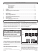
TABLE OF CONTENTS A. B. C. D. E. F. G. H. I. J. K. L. M. N. Safety Precautions ............................................................................................................................... 2 Introduction .......................................................................................................................................... 3 Burner Model Number .............................................................................................................
sure. For gas firing, the gas manifold pressure is given in “in wc” which is inches of water column. The electrical ratings of the burner are given, with the voltage, current load, frequency and phase (this will either be single or 3-phase). For motors, the motor HP is listed. 2. Ratings e. Catalog cuts of the major components. These provide details on the installation, adjustment and maintenance of the components used on the burner. 5.
MODEL JB(X) BURNER MODEL CONFIGURATION FIGURE A-2 JBX1G -05-RM7800L-M.
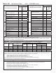
Model JB1 - Specification Data (400 - 2500 MBH Input) X X Air Flow Switch (also with oil systems using remote pump) X X X Flame Safety Control X X Ultra Violet Scanner X X Motor Controller (single phase voltage) X X Switch and Indicator Lights Optional Ignition Fuel Selector Switch Main Manual Shutoff Valve X Main Safety Shutoff Valve X Second Safety Shutoff Valve X Main Gas Regulator X Gas Checking Valve X High and Low Gas Pressure Switches (st’d over 2500 MBH) Duel Fuel Burne
Model JB1 - Dimentional Data (400 - 2500 MBH Input) (Dimensions are +/- 1/4 inch) 9 1/2 24 5 5/16 4 26 5/8 8 1/4 10 15 18 3/8 15 11/16 Standard Arrangement Elevation 11 7/16 21 7/8 Standard Arrangement End View 4 36 15/16 36 15/16 4 14 3/8 18 3/8 7 1/4 O.D.
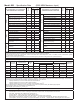
Model JB2 - Specification Data (6000 MBH Maximum Input) No.
Model JB2 - Dimensional Data (6000 MBH Maximum Input) (Dimensions are +/- 1/4 inch) 6 1/2 24 28 5/8 5 5/16 4 9 1/2 10 15 19 1/16 19 17 3/4 Standard Arrangement Elevation 30 11/16 Standard Arrangement End View 4 39 1/4 4 39 1/4 14 18 1/2 19 1/2 9 1/8 O.D.
Model JB3 - Specification Data Air Atomized N0. 4 - 6 Oil Air Atomized No.
Model JB3 - Dimensional Data (12,600 MBH Maximum Input) (Dimensions are +/- 1/4 inch) 6 1/2 24 4 38 1/4 5 5/16 15 15/16 10 15 19 15/16 22 1/2 16 Standard Arrangement Elevation 27 Standard Arrangement End View 48 4 22 1/2 48 4 19 1/4 Standard Arrangement Elevation W/ Optional Back Mount Control Cabinet 19 9/16 11 1/4 O.D.
B. COMPONENT IDENTIFICATION This secion shows the different common components used in the JB burner line and should be helpful to identify parts described elsewhere in this manual.
Board to Light Panel Cable Combination Flame SafeGuard Base and Circuit Board Switch / Light Panel Light Panel Circuit Board Flame SafeGuard Base Figure B-4 Control Panel Circuit Board Design Field Wiring Terminal Strips Panel Wiring Terminal Strip Board to Light Panel Cable Electrical Panel Identification: The above pictures show the flame safeguard base mounted on a circuit board. Connections are wired via cable to light / switch circuit board.
Air Inlet Louver Box Electrical Junction Box Oil Cam Low Atomizing Air Press. Sw. Drawer Assembly Jack Shaft Atomizing Air Bleed Muffler High Oil Temp. Switch Air Bleed Valve Atomizing Air Press. Gauge Blower Motor Oil Temp. Gauge Atomizing Line to Nozzle Supply Oil Press. Gauge Oil Metering Valve Trim Heater Safety Relief Valve Trim Heater Drawer Assm. Pre-heat Oil Lines Oil Supply To Nozzle Thermostat Control Switch & Cold Oil Interlock Switch N.O. Return Oil Valve Nozzle Oil Press.
Mounting Flange Gas Manifold Orifice Plate Secondary Gas Orifices Nose Choke Cone Primary Gas Orifice Drawer Assembly Retention plate Assembly Ignition Electrode Diffuser Figure B-9 Standard Head Arrangement Section View Pilot Assembly Gas Inlet Gas Manifold (inner cylinder) Retention Plate Assembly This connection between the retention plate assembly and the gas manifold inner cylinder must be properly made for proper performance.
Oil Supply Line View Port Oil Ignition Electrodes Diffuser Oil Nozzle(s) Oil Supply Line Back Plate Oil Nozzle(s) Adapter Sight Tube Diffuser Clamp Figure B-12 JB1 & 2 Straight #2 Oil Drawer Assembly with Direct Spark Ignition Gas Orifice Part Number and Description Sketch Example Vessel Gas orifice, 5/16” brass, (2) radial #48 holes, no axial hole (48 x 2) B FB 090002-098 Gas orifice, 5/16” brass, (2) radial #40 holes, no axial hole (40 x 2) B FB 090054-xxx Gas orifice, 5/16” brass, no radia
C. INSTALLATION Prior to installing the burner, the site conditions and utilities need to be evalulated. This section provides some general questions that can help the review process. Inspect the burner for any undetected damage that may have occurred during shipment or by job-site handling. Special attention should be given to the control panel and protruding parts such as linkages. Check linkages, air louver stops, wiring connections and fasteners for tightness.
Pilot Shutoff Valve Pilot Gas Pressure Regulator Pilot Solenoid Valve Normally open vent valve Gas Supply Low Gas Pressure Switch Gas Pressure Regulator High Gas Pressure Switch Manual Gas Shutoff Valve Burner Shutoff Valve Shutoff Valve If applicable, Webster supplied gas train Leak Test Valve Figure C-1 Typical Gas Piping Drip Leg Chart C-2 Chart C-3 TYPICAL COMBUSTION CHAMBER SIZE FOR SCOTCH MARINE FIRETUBE BOILERS th Leng gth Len Width ner enter of Bur t - Floor to C Heigh ter Di
E. BURNER MOUNTING CRITERIA It is of vital importance that the burner be properly mounted to the boiler or appliance being fired. Improper mounting can cause leakage of the hot gases back around the burner head resulting in warpage and deterioration. The following illustrations show the proper way the burner must be installed to validate warranty conditions. TYPICAL JB1, 2, 3 BURNER REFRACTORY FRONTPLATE B - Bolt Circle Use minimum of four (4) 1/2” studs with lugs.
F. FUEL SYSTEMS The JB burner can be equipped with a wide range of fuel and operating systems to control the fuel, air, modulation and pilots. This section describes how these systems operate. Burner start-up is expected to be done by service personnel who are qualified in the basics of mechanical know-how. The following illustrations and information is supplied to identify the various fuel; air and ignition devices that have Adjustment Features.
“MP” - Modulating Simplex Nozzle 2 Low Oil Pressure Switch Oil Metering Valve 1 1 Oil Nozzle Gauge Port Adjustment Oil Pump Check Valve Return to Tank, (No Manual Valves in this Line) Main Oil Safety Oil Solenoid Valve Solenoid Valve 1 By Others Shutoff Valve Suction Supply Line Field Piped Notes & Options Check Valve Strainer By Others (Unless Specified on Order) 1 These Lines are Field Piped if a Remote Pump is Used 2 Usage Requirement Varies with Code “MR” - Modulating Return Flow Noz
2. Air Atomized Oil Systems Safety Valve Air Filter Ball Valve (man. set to adjust air volume & high fire air pressure) Air pipe same size Low as discharge open- Atomizing ing in air chamber Pressure (field Piped) Check Gauge Valve Compressor Pressure Gauge Oil Metering Valve Low Oil Pressure “MA” - Modulating #2 Oil Air Chamber Safety Oil Valve N.C.
3. Gas Systems Illustrated Gas Trains by Capacity and Code: The following illustrations show the Webster configuration for UL, FM and IRI as grouped by UL capacity ratings. Refer to the legend below for component part identification. These illustrations are not to be used for field erection and/or system design purposes. UL Capacity Range BTU/Hr.
722001 Field Piped Pilot Gas Pressure Regulator Pilot Manual Ball Valve Pilot Solenoid Valve Gas Pilot Ignitor S Vent To Outside Atmosphere Gas Supply Main Motorized Gas Valve 26 Sec.
722009 Field Piped Pilot Manual Ball Valve Pilot Gas Pressure Regulator S Vent To Outside Atmosphere Gas Supply Manual Ball Valve Pilot Solenoid Valve Man Reset Low Gas Pressure Switch Main Motorized Gas Valve 14 Sec. M L Gas Pressure Manual Test Regulator Valve M Field Piped Man Reset High Gas Pressure Switch Vent Main Motorized Gas Valve 26 Sec.
722010 Field Piped Pilot Manual Ball Valve Pilot Gas Pressure Regulator S Vent To Outside Atmosphere Gas Supply Pilot Solenoid Valve Gas Pilot Ignitor Man Reset Low Gas Pressure Switch Vent Main Motorized Gas Valve 26 Sec. Main Mortorized Gas Valve 14 Sec.
722084 Field Piped Pilot Manual Ball Valve Gas Pressure Regulator Gas Supply Manual Ball Valve Pilot Gas Pressure Regulator Pilot Solenoid Valve S Vent To Outside Atmosphere Gas Pilot Ignitor Normally Open Vent Vent Valve Main Motorized Main Motorized Gas Valve Gas Valve W/POC W/POC - 14 sec. 14 sec.
G. INITIAL SETTINGS The burner will be set at the factory for normal initial settings. These are only rough settings that must be adjusted at startup to match the furnace, fuel pressure and environment of the specific application. These general settings are covered in this chapter as a means of checking the burner (linkage and settings can move in shipment) or readjusting the burner if the settings are lost. 1. Oil nozzle position The oil nozzle initial position is shown in Figure G-2.
COMBUSTION AIR CONTROL 2. AIR PROVING SWITCH Panel The air proving switch has been adjusted at the factory for an initial setting. If the switch trips during initial startup, turn the adjustment screw ccw two full turns to reduce the trip pressure setting. Adjusting Screw Air Proving Switch AIR FLOW INTERLOCKING SWITCH 3. TYPICAL AIR AND FUEL ADJUSTMENT LOCATIONS 4. Fuel Cam Adjustments (if applicable) The fuel cam needs to be checked for correct travel and alignment.
H. IGNITION SYSTEMS Electrode Spark Gap = 1/16” Electrode Clamp Pilot Figure H-1 JB1 & JB2 Gas Pilot Figure H-2 JB3 PILOT ASSEMBLY 1. Gas Pilot Assembly A crucial part of reliable burner operation is a dependable pilot, which must be properly adjusted and kept clean. A gas pilot is standard for all models except JB1 through JB2-20 straight oil pressure atomizing burners which have direct spark ignition as standard.
Figure H-3 7/8” Figure H-4 (3 1/2”) (2 1/2”) FIGURE H-5 DIRECT SPARK PRESSURE ATOMIZING OIL IGNITION (SEE TABLE BELOW) Diffuser ID Note: These represent initial nozzle settings. The final position will be determined in the start-up process.
1. 2. 3. 4. 5. 6. 7. 8. 9. 10. 11. 12. 13. 14. 15. 16. 17. 18. I.
Low Fire A ible strip is required to move to a screw position where it is initially not in contact with the screw. Also, the movement from one screw to the next cannot be too large (more then 1/8”). This will cause the strip to flex and will lead to premature failure of the strip. d. The adjusting screws have a limited range of adjustment. They can be turned in until they are flush with the aluminum bar and adjusted out until the side washers of the roller contact the aluminum bar. e.
equipped with Posi-Control can be adjusted for individual air and FGR settings on both fuels and can easily handle these variations, even with lower NOx levels. Linkage burners operating at 30 ppm NOx (natural gas) are equipped with a potentiometer in the control panel that will allow the shut-off valve to partially open and allows a small amount of FGR to flow when firing oil. This keeps the oil inputs close to the gas input (lower FGR rates increases the combustion air rate).
Combination burners, firing both gas and oil, require some compromises in the setup because they share common controls for both fuels. In this case, linkage units must have the gas input adjusted to match the oil inputs because there is little flexibility in adjusting the oil rates. Oil will be setup first and will set the air damper positions to support the low and high fire oil inputs. Follow the procedure outlined in section 11 to complete the oil setup.
valves must be visually checked by observing the valve stem operation. k. After the timer has completed the trial for main flame, the burner will go out on alarm (the closed manual gas valve prevented the burner from lighting). At this time, the gas valves must be visually checked to verify that they have closed. This test sequence proves the proper operation of the primary control. l. Press the reset button and restart the burner.
Natural Gas With FGR Figure I-3 O2 levels Oil % Rate Min % O2 Max % O2 Min %O2 Max %O2 Min %O2 Max %O2 30 5.0 7.0 5.0 7.0 3.5 7.5 40 4.0 7.0 4.0 7.0 3.0 7.0 50 3.0 5.0 3.0 5.0 3.0 5.0 100 3.0 5.0 3.0 5.0 3.0 5.0 the highest expected gas pressure. • With a gauge or manometer at the same location as the high gas pressure switch, modulate the burner to determine the firing rate with the highest gas pressure.
m. At high fire (end of the modulating motor travel), adjust the high fire input (open or close the fuel valve) to match the maximum input and/or pressure listed on the rating label. The fuel metering valve should be nearly closed (or closed) at this point and the nozzle pressure should be about 150 PSIG (return line) for JB3. For JB1 and JB2 250 to 300 psig. n.
Gal start = gallons at start of the test Measured sec = measured time of test GPH = Gallons of oil per hour n. If equipped with FGR, adjust the NOx level to be about 10% below any guaranteed NOx performance or if no performance guarantee exists adjust the FGR to provide some added turbulence but not high enough to impact flame stability. A balance of the FGR control valve and air damper are required to obtain the final result, as each can impact the other.
be measured using the following equation, about which limits are on a burner, refer to the wiring diagram that will show each item. Oil GPH = [Gal end – Gal start] x [3600 sec/hr] / [measured sec] Limit switches need to be checked at regular intervals to ensure they are operating properly. See the maintenance section for details. Where Gal end = meter gallons at end of test Gal start = gallons at start of the test Measured sec = measured time of test GPH = Gallons per hour 16. Pilot Test o.
the location of the pilot and scanner, as shown in section “H”. This may also indicate a faulty scanner or amplifier. 17. Burner Shutdown Normal operation of the burner will allow the operating controls to shut the burner down when the load demand is satisfied. If the burner needs to be shut down for any reason, the “ON-OFF” switch can be used to quickly turn the burner off. This will instantly cause the fuel valves to close and start a post purge cycle to remove any unburned fuel from the vessel.
J. TROUBLESHOOTING No. 1 2 3 4 5 6 7 8 9 System Cause Correction No Ignition Electrode is grounded. Porcelain is cracked.
No.
No. 16 17 System Cause Correction Cannot obtain rated input on Oil pressure too low Increase oil pressure oil firing (pres. atom.
K. GENERAL MAINTENANCE AND CARE 1. 2. 3. 4. 5. 6. 7. General Physical Inspection Fuel-Air-Ratio Gas Fuel Systems Oil Fuel Systems FGR System Combustion Air Fan There are several different types of controls and the corrective action of each could be different. The following general guidelines can be used for initial steps. Linkage based controls should be inspected for wear. If there is any noticeable play in the linkage rod ends or shaft bearing, they should be replaced.
a good seal. The basket can be lifted out and cleaned with a soft brush and cleaning solution. d. Vacuum higher than the 10” limit on suction side of pump (indicates need to clean strainer, as described above). If cleaning the strainer does not resolve this, check the other valves between the tank and gauge for plugged or closed position. e. Air atomized oil nozzles should be cleaned periodically, depending on the type of operation and the observed need for cleaning.
8 - Inspection and Maintenance Schedule Recommended Action or Test Trained Burner Technician Component / Item Boiler Operator Performed By Annual As Required Annual Seasonal Weekly Monthly Daily Frequency X Burner Flame Visual inspection of burner flame. X X Jackshaft and Linkage Visual inspection for smooth and free travel. X X Air Damper Visual inspection for smooth and free travel. X X Fuel Metering Valves Visual inspection for smooth and free travel.
L. CARE OF THE BURNER DURING EXTENDED SHUTDOWN Heating equipment is oftentimes located in an environment conducive to corrosion and general deterioration if not properly protected and periodically checked, especially during an extended period of shut down. The following procedures should be followed if the burner is going to be placed out of service even for a short period of time. 1. Turn the main manual fuel valve OFF.
WARRANTY VALIDATION FIELD START-UP REPORT CUSTOMER:_________________________________ W.O. _________________ BURNER MODEL: ____________________________ BOILER MODEL: ________________________________ CONTROL CIRCUIT COMPONENT OPERATIONAL TESTING (Check if Okay) Primary LWCO _______________ High Limit ____________________ Secondary LWCO _____________ Operational Control ____________ High Gas Press. Switch _________ Oil Press. Switch ______________ Low Gas Press.
NOTES JB Manual Page 50 Notes
NOTES JB Manual Page 51 Notes
NOTES WEBSTER ENGINEERING & MANUFACTURING CO., LLC 619 Industrial Road - Winfield, KS 67156 Phone 620-221-7464 Fax 620-221-9447 sales@webster-engineering.com service@webster-engineering.com www.webster-engineering.