
Owner manual

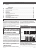


(1) STANDARD UL
EQUIPMENT
AND IMPORTANT OPTIONS
Gas
No. 2 Oil
No. 4 - 6 Oil
Air Atomized
STANDARD UL EQUIPMENT
AND IMPORTANT OPTIONS
Gas
No. 2 Oil
N0. 4 - 6 Oil
Air Atomized
Pressure
Atomized
Air
Atomized
Pressure
Atomized
Air
Atomized
General
Motor, Fan and Air Inlet Control X X X X
Gas Fuel
Main Manual Shutoff Valve X
Air Flow Switch X X X X Main Safety Shutoff Valve X
(2) Burner Mounted Control Panel,
Switch and Four Indicator Lights
X X X X
Second Safety Shutoff Valve
X
Main Gas Regulator X
Flame Safety Control X X X X Gas Checking Valve X
Ultra Violet Scanner
X X X X High and Low Gas Pressure Switches X
Motor Starter with Overloads X X X X Metering Valve (modulating systems) X
Fuel Selector Switch Duel Fuel Burners Only Normal Open Vent Valve (above
12,500 MBH)
X
Ignition
Proven Gas Pilot Ignition X X X
Oil Fuel
Oil Drawer Assembly with Diffuser X X X
Pilot Solenoid Gas Valve
X X X Oil Nozzles X X X
Pilot Gas Regulator & Manual Valve
X X X Oil Heater with Integral Thermostat X
Pilot Gas Ignition Transformer
X X X Remote Oil Pump X Opt. Opt.
Two Safety Shutoff Valves
X X X
High Oil Temperature Switch
X
Low Air Atomizing Switch
X
Options
Inverted Housing X X X X Low Oil Pressure Switch X X X
Alternate Control Cabinet Positioning X X X X Oil Pressure Gauge X X X
Remote Control Panel X X X X Oil Metering Valve X X X
Fuel Metering CAM-NETIC II X X X X Future Gas Combustion Head Opt. Opt. Opt.
Posi-Control X X X X Air Compressor X X
1. The configuration of each unit will vary with specific job requirements such as input rating, electrical specification and special agency approval codes.
The above chart shows those items standard to a basic burner plus a few options that may be added.
2. Indicator lights are “Power On”, “Call for Heat”, ”Fuel On” and ”Flame Fail”.
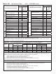
Model JB3 - Sizing and Application Data (contact Webster for complete information)
Model
Number
Maximum
Furnace
Pressure
Burner Firing Capability Range Burner
Motor
HP
Gas Train
#2 Oil Pump Motor HP #4 - 6
Pump
Motor HP
Air
Compressor
Motor HP
Pipe
Size
Inlet
Press
Pressure
Atomizing
Air
Atomizing
Gas scfh #2 Oil
gph
#4-6
Oil gph
JB3-30 3.5 1400 / 6300 10.2 / 45 10 / 42 3 2 1/2” 12 / 27” 1 Optional Optional 2
JB3-50 3.5 1400 / 8300 11 / 59.2 10 / 55.3 5 3” 15 / 27” 1 1/2 Optional Optional 2
JB3-75 3.5 1600 / 10500 12.3 / 75 11 / 70 7 1/2 3” 23 / 27” 1 Optional Optional 2
JB3-100 3.5 1800 / 12600 20.3 / 90 12 / 84 10 3” 2-5 psi 1 Optional Optional 2
The above maximum ratings are based on 0 furnace pressure, an altitude of 1000 feet, 90
o
F air temperature and 60 HZ electrical supply. Use the follow
-
ing corrections for higher temperatures and altitude. Capacity by 17% for 50 Hertz.
Capacity decreases by 4% for each 1000 feet above 1000 foot altitude.
Capacity decreases by 6% for each 1 inch of furnace pressure.
Capacity decreases by 2% for each 10
o
F increase in air temperature over 90
o
F.
Gas input ratings based on 1000 BTU/cu ft. and 0.64 specific gravity. Sizes and pressure will vary with gas.
Oil input ratings are based on 140,000 BTU/gal. for ASTM #2 fuel oil and 150,000 BTU/gal for ASTM #4-6 fuel oil.
The vessel draft must be between -0.1 and +0.1 wc.
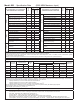
Essential Ordering Information and Data:
Power Supply - Confirm 120-60-1 for control circuit and electrical supply for burner motor(s) (voltage, frequency and phase).
Describe Boiler or Heater to be Fired - Including the manufacturer, model number, furnace pressure and furnace size.
Firing Rate - Define firing rates in MBH for gas and GPH for oil.
Fuel to be Burned - Type of gas and/or oil, including the BTU value.
Approval Agency - UL, FM, IRI (GE GAP), CSD-1, NFPA, Mil spec and local codes, if applicable.
Flame Safety Control Preferred - Honeywell or Fireye controls.
Gas Train Components Preferred - ASCO/ITT, Honeywell or Landis
Control System - ON-OFF, Low Fire Start, Low High Low, Modulation, Posi-Control
Required Options - Mounting plate, operating controls, limit controls, etc.
Model JB3 - Specification Data (12,600 MBH Maximum Input)
Page 10
Specification
JB Manual