
Install Instructions

Mounting
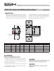
1. Remove the entire front cover (PSC versions) by extracting 2 screws on top front.
2. Attach uncovered power supply using 4 screw holes.
3. Make desired wire connections.
4. Reattach cover for PSC versions.
Wiring
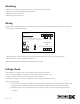
All wiring must comply with local codes and ordinances. Disconnect power before making wiring connections to prevent
electrical shock or equipment damage.
Hot Neut
Gnd AUX
120V INPUT
24 Vac LED Indicator
Class 2, 12-18 AWG, 10 lb./in max, copper 60ºC
TRANSFORMER:
24Vac, 100VA, Class 2
Note
Convenience Outlets & Aux. Load:
120Vac, Total Load not to exceed 9A
*
Move internal jumper to “ALWAYS HOT” position if you wish outlets
to always be hot otherwise outlets will be switched by main breaker.
OUTPUT
See Note
COM 24 VAC
RESET
OFF
RESET
120Vac
10A Main
24Vac for Output Only
24Vac
Breaker
ON
OFF
Class 2, 12-18 AWG, 10 lb./in max, copper 60ºC
1. Bring wiring into 1 of the 2 openings on the side of the power supply while cover is removed (PSC version).
2. Make appropriate connections to the terminal strips.
Note: All eld wire leads are intended for installation inside the enclosure.
Voltage Check
After installation is complete, turn on power supply and perform a voltage check:
1. Place controlled equipment in operation and observe through one complete cycle.
2. Using a voltmeter, check for proper primary and secondary voltages.
3. If voltage readings are incorrect, be sure primary voltage connections are made correctly.
4. Measure voltage again:
a. If correct primary voltage is measured and secondary voltage is signicantly less than the voltage shown on the
regulation curves, transformer winding is damaged. Replace transformer and repeat checkout procedures.
b. If primary voltage is 0V, be sure power supply is connected correctly or repair, if necessary. Repeat checkout
procedures.
393170B 02.25.13