
Safer Choice Standard


Report No. 130815040GZU-001
IMPERIAL INDUSTRIAL SUPPLY
Page 32 of 33
Issued: 23-Dec-2013
Revised: None
Product
Test Voltage
Test Time
All products covered by this Report. 1000V 60 s
or
1200V 1 s
Each product listed below shall be subjected to a test to determine that there is continuity between accessible
dead-metal parts of the product and the grounding pin or blade of the attachment plug.
If all accessible dead metal is connected, only a single test need be performed. A visual or audible device
(ohmmeter, buzzer, etc.) may be used to indicate grounding continuity.
Products Requiring Grounding Continuity Test:
All products covered by this Report.
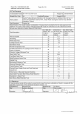
11.0 Manufacturing and Production Tests
The manufacturer agrees to conduct the following Manufacturing and Production Tests as specified:
Required Tests
11.2 Grounding Continuity Test
Method
If the rated output of the test equipment is 500VA or more, the applied test potential may be indicated by either:
1 - a voltmeter in the primary circuit;
2 - a selector switch marked to indicate the test potential; or
3 - a marking in a readily visible location to indicate the test potential for test equipment having a single test
potential output.
In cases 2 and 3, the test equipment shall include a lamp or other visual means to indicate that the test potential
is present at the test equipment output. All test equipment shall be maintained in current calibration.
Products Requiring Dielectric Voltage Withstand Test:
Dielectric Voltage Withstand Test
Grounding Continuity Test
11.1 Dielectric Voltage Withstand Test
Method
The test voltage specified below shall be applied between primary circuits and accessible dead-metal parts. The
test voltage may be gradually increased to the specified value but must be maintained at the specified value for
one second or one minute as required.
One hundred percent of production of the products covered by this Report shall be subjected to a routine
production line dielectric withstand test.
The test shall be conducted on products, which are fully assembled. Prior to applying the test potential, all
switches, contactors, relays, etc., should be closed so that all primary circuits are energized by the test potential.
If all primary circuits cannot be tested at one time, then separate applications of the test potential shall be made.
The test equipment shall incorporate a voltmeter in the output circuit to indicate directly the applied test potential
if the rated output of the test equipment is less than 500VA.
Test Equipment
The test equipment shall incorporate a transformer with an essentially sinusoidal output, a means to indicate the
applied test potential, and an audible and/or visual indicator of dielectric breakdown.
ED 16.3.15 (1-Jan-13) Mandatory