
User Manual


6
IT-RefeRence 20i OwneR’s Manual
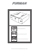
For rack mounting that will be transported, rear rack mounting is recommended due to the high mass of the IT-Reference 20i.
These rear rack kits are not necessary for a stationary installation. They are available from your Furman dealer as an optional
accessory. The rear rack mount kit model number is: RRM-3 REF.
Connection
AC Cable Routing
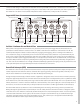
Once the IT-Reference 20i is placed, its AC cord’s female end must be plugged into the male IEC connector located on the lower
left hand side of the rear panel (when facing the rear panel). Next the male Edison plug must be connected to an appropriate
socket (see current rating recommendation above). This AC cord will carry substantial unbalanced AC current, so it should be
dressed away from critical signal-carrying cables, or at the very least, cross them at a 90 degree angle. The same is true of the
power amplier AC cords when plugged into the IT-Reference 20i’s “High Current - Amplier Power” AC ltered outputs. All other
components plugged into “Discrete Symmetrical Power” outlets (A) through (D) have symmetrical AC current and will radiate
virtually no eld; as a result of this technology, their placement is not critical.
Connecting Components to the Symmetrical Power Banks
The IT-Reference 20i’s “Symmetrical Power Outlets” should be employed for all components other than receivers with power
amplication, power ampliers, powered subwoofers, or powered loudspeakers. Each “Discrete” bank (A) through (D) contains
two parallel outputs that are symmetrically balanced, ltered, and totally isolated from adjacent output banks or the (4) “High
Current - Amplier Power” outlets. It should be noted that as each AC bank’s outlets are in parallel, component power supply
noise could potentially “back-wash” between these units.
For this reason it is recommended that systems with minimal components (four units or less, excluding the power ampliers)
utilize one “Discrete bank” per component. This will maximize performance by eliminating inter-component AC noise
contamination entirely! For systems utilizing more componentry, high performance will still be achieved with careful routing of
component AC cords to the IT-Reference 20i’s four “Discrete” power banks. We recommend separating digital processors, DVD’s,
and CD players from pre-ampliers, tuners, and tape machines. Further, video monitors and scalers should ideally be separated
from audio components.
Connecting Components to the High Current Power Amplier Banks
Many audiophile and premium home theater systems will have combined continuous current demands far below 20 Amps. It is
rare, in fact, for large power ampliers to draw more than 4 Amps continuously.
For superior performance, it is vital that an AC lter possess extraordinarily low impedance, and have the capability to pass peak
current demands far in excess of the RMS (continuous) current rating. The IT-Reference 20i was designed to more than meet this
demand. Additionally, our Power Factor Technology circuitry eectively creates a current reserve in excess of 80 amps peak up-
charge that is cleaner and more ecient than a dedicated line from your local power station. This feature eliminates any concern
with the current compression that can result from typical power conditioners. In fact, Furman’s Power Factor Technology
circuitry provides lower AC impedance with current on demand which benets any power amplier’s performance dramatically.
Note about Power Factor Technology and Current Consumption
When Power Factor Technology is employed (transient or RMS), even the most sophisticated circuit breakers will perceive an
increased current load. Though the IT-Reference 20i was designed for steady 20 Amp operation, and peak current demands
many times that, the maximum total continuous current draw may be limited to a range between 1500 - 2100 Watts per IT-
Reference 20i employed.
The RMS current available before the circuit breaker trips varies greatly due to what is referred to as a vector load. Simply put,
the type of power supplies or electronic circuits connected to the IT-Reference 20i will have an eect on its circuit breakers
perceived current load, and therefore, when it will trip. Though the benets of Power Factor Technology far outweigh the small
reduction in continuous current draw, this must be accounted for when constructing a large system with high current demands.
The total continuous current draw of most electronic components is typically listed in Watts by their AC input cord or AC