
Owner's Manual


REAR PANEL FEATURES (continued)
Remote
Interface
The M-8S has a remote interface which can be used
to control the M-8S remotely using a Furman
RS-1
(Maintained)
or
RS-2 (Momentary) wall switches.
In
the most basic, single unit configuration, only two
wires and a switch are required to initiate a remote
ON
or
OFF sequence. The switch may be either a
momentary
or
maintained-contact type. If a third &
fourth wire are available,
an
LED "Status Light" can
be installed at the remote switching location to indi-
cate the status
of
the M-8S. The pins on the remote
interface are described below:
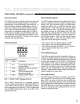
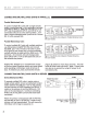
Remote
Interface
0000
T T T T
12V
STAT
REM
GND
REMOTE
PORT
Remote Interface
Pin Label
Description
1 12V
12VDC @12mA General
Purpose Output
2
STAT Output for driving
an
external
status LED
3 REM
Input for controlling the
sequencer remotely
4 GND Ground (12VDC Power
Common)
PIN 1 +12VDC (12VDC Voltage
Source)
The +12VDC terminal pin is a general purpose,
12VDC voltage source relative to the GND (#4) pin. It
is provided to allow the user to control the operation
of
the sequencer by feeding the +12VDC signal back
into the REM terminal input; which is pin #3 on the
same barrier strip.
PIN 2 STATUS
(Output)
The STAT (status) terminal is an output that may be
used to activate an LED to indicate the status
of
the
M-8S. If the STAT terminal is high, the M-8S Delay
outlets are either ON,
or
are
in
the process
of
se-
quencing ON. If the STAT terminal is low, the M-8S
Delay outlets are OFF.
To
use the STAT terminal out-
put simply connect an LED between the STAT and
GND with the Cathode (flat) side
of
the LED oriented
toward the GND pin (Pin #4). Do not use a series cur-
rent limiting resistor. If the LED does not light when
the remote switch is ON, check the polarity
of
the
LED and reverse the leads if necessary.
• If the LED is OFF, the DELAY outputs are OFF
• If the LED is ON, the DELAY outputs are ON
• If the LED is blinking, the DELAY
1,
2 or 3 outputs
are
in
transition either from ON to OFF
or
OFF to ON
PIN 3 REMOTE
(Input)
The REM (remote) terminal is provided to allow re-
motely connected devices to sequence the M-8S ON
or
OFF.
The M-8S' REM terminal has been designed
to work with voltages from 5 to 30VDC. Filtering has
been added to this input to prevent false-triggering.
The behavior
of
the M-8S is controlled by the com-
bination
of
the signal presented at the REM terminal
input, and the arrangement
of
the rear panel DIP
switches. Please refer to REAR PANEL DIP SWITCH
section (page 6) for more details.
PIN 4 GND (Power)
The GND (ground) terminal pin serves a ground ref-
erence point for all other pins on the Remote Inter-
face. GND can also be fed back into the REM pin
(Pin #3) to activate the sequence when the M-8S has
been configured for GND ON mode. Please note that
the GND terminal on the Remote Interface is not the
same as chassis ground and should never be con-
nected to chassis ground.
5