
Selection Guide

Class 69W Pressure Switch - Water Systems
4269W
Electrical Ratings
69W Water Systems
Hubbell Industrial Controls, Inc.
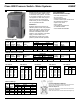
Class 69W Pressure Switch–Water Systems
Catalog 4269W • March 2011, Replaces August 2005
Hubbell brand W series pressure switch-
es provide time tested, reliable control
for automatic water systems. The switch
is universally accepted for use as origi-
nal equipment on water well pumps or
pumping systems. Its simple design
makes it easy to use for professionals
and non-professionals alike.
GARD-ALL®
Switches combine the functions of a
standard pressure switch with protection
against low pressure. They prevent the
pump from starting whenever the sys-
tems falls considerably below cut-in
pressure. Upon restoration of the water
supply, a manual reset lever is
depressed until a build up of system
pressure permits automatic operation.
Class 69W Switch
Standard Features Include:
• Corrosion resistant cover
• No wire looping
• Straight through wiring
• Visible contacts–2 pole, double throw
• No-drift pressure settings
• Captive cover screw
• Easy to adjust
• Two ratings–3 HP and 5 HP
• UL listed file #14861
• CSA certified file #LR36854
4269W
Application
Min. Max. Pressure Setting
Horsepower
NEMA 1
Close Open Differential Adjustment 1 Phase 3 Phase Factory General Purpose
Cut-In Cut-Out Range Table
120V 240V 240V 480/600V
Setting Cat No.
5 psi 65 psi 15-30 psi A 1.5 2.0 3.0 – 30-50 69WA4
5 psi 80 psi 15-30 psi B 2.0 3.0 5.0 1.0 30-50 69WB5
3 psi 35 psi 6-15 psi C 2.0 3.0 5.0 1.0 5-10 69WB3
1 psi 12 psi 3-5 psi D 2.0 3.0 5.0 1.0 3-7 69WB2
Horsepower
Cat. Control 1 Phase 3Phase DC
No. Circuit 112V 240V 240V 480-600V 32V-230V
69WA A600 1.5 2.0 3.0 – 1/4
69WB A600 2.0 3.0 5.0 1 1/2
69WE A600 1.5 2.0 3.0 – 1/4
69WF A600 2.0 3.0 5.0 – 1/3
69W with Low Pressure Cut-Off
Min. Max. Pressure Setting
Horsepower
NEMA 1
Close Open Differential Adjustment 1 Phase 3 Phase Factory General Purpose
Cut-In Cut-Out Range Table
120V 240V 240V 480/600V
Setting Cat No.
10 psi 70 psi 13-30 psi Q 1.5 2.0 3.0 – 20-40 69WEC
10 psi 70 psi 13-30 psi Q 2.0 3.0 5.0 – 20-40 69WFC
PSI Table A
Cut-In Cut-Out–B
A Min. Max.
5 15 35
10 21 40
20 32 50
30 43 60
40 53 65
50 64 65
PSI Table B
Cut-In Cut-Out–B
A Min. Max.
5 19 35
10 25 40
20 35 50
30 45 60
40 55 70
55 66 80
60 76 80
63 80 80
PSI Table C
Cut-In Cut-Out–B
A Min. Max.
3 9 18
5 11 20
10 16 25
15 21 30
20 26 35
25 31 40
PSI Table D
Cut-In Cut-Out–B
A Min. Max.
14 6
2 4.25 7.25
3 5.25 8.50
4 6.25 9.50
5 7.50 10.75
6 8.50 11.75
PSI Table Q
Cut-In Cut-Out–B
A Min. Max.
10 23 40
20 33 50
30 43 60
40 55 70
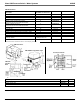
Pressure Adjustment Settings
Screw A–Turn clockwise to increase and counterclockwise to
decrease pressure range (both cut-in and cut-out).
Differential Adjustment
Screw B–Turn clockwise to increase and counterclockwise to
decrease cut-out pressure.
NOTE: Differentials shown on tables above are averages only.