Assembly Instructions ASSEMBLY RATING Tools Required for Assembly: The Assembly Rating isa B-point system that shows the degree of effort needed in assembling a specific product (with 1 being ini § Te easy and & being difficult. Formosa Philips Screwdriver ot studied) products, two persons are recommended.
90-DAY LIMITED REPLACEMENT PARTS WARRANTY This item comes with a 90-day limited replacement parts warranty to the original purchaser of new products against defects in materials aid workmanship for a period of ninety (90) days from the date of receipt. This warranty is not transferable.
ASSEMBLY & CARE ADVICE FOR YOUR FURNITURE TO LAST, CORRECT ASSEMBLY AND PROPER MAINTENANCE ARE NECESSARY. PLEASE FOLLOW THE INFORMATION PROVIDED BELOW TO FULLY ENJOY YOUR FURNITURE. BASIC ASSEMBLY TECHNIQUES Hyde highly recommended halt assembly Should BE Dane nerd the arts of fs intended location, Make Sif yeu Have Sad Ugh Space To move around during the assembly ALLAYS have 81 sas in people te Bast with trans porting snd fricasseeing {hie protract ta avid any potential infancy landlord damage.
PER-ASSEMBLY INTRODUCTION Unless your are particularly adept at assembling flat-antiknock-down furniture ‘we understand building ready-to-assemble failure bean frustrating experience for some. To help avoid confusion and to make the assembly process quicker and smoother we have provided some helpful tips. Before you begin the assembly.
CAM LOCK FASTENER ASSEMBLY INSTRUCTIONS Note: Every cam lock bolt must have a cam Jock connector in order to fasten the parts together, {fH Align the cam connector with its Secure the threaded i side opening (or arrow) end of the cam bolt pointing to the small by using a drilled hole. screwdriver. i < Turn right (clockwise) to tighten, Two parts should fit snugly (3) against each other. Insert the cam lock bolt into the per-drilled hole above the cam connector.
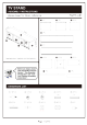
TV STAND ASSEMBLY INSTRUCTIONS please keep for future reference PARTS LIST o orc @ specs DIMENSIONS: 70.86" Beforehand, please (ead Assembly dnd Cag Advice”, “Assemblymen Introduction” and “Cam Look Fastener Assembly Instructions”. HARDWARE LIST PCS (2) PCS @) PCs 0.
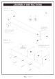
ASSEMBLY INSTRUCTIONS STEP : 1 Hardware (1) x PCS Hardware (4) x PCS Hardware (8) x PCS Use dowels (#5) on panels (#A B} Use dowels (#4) on panels (#E 1).
ASSEMBLY INSTRUCTIONS STEP: 4 Hardware (2) x PCS One line gap facing down for panels {#A BE) STEP: 5 Hardware (8) x PCS ym note Page goof 13 Two line gap facing up on > Finished side facing up for ali panel
ASSEMBLY INSTRUCTIONS STEP: 8 Hardware (2) x PCS Hardware (3) x PCS Hardware (8) x PCS Hardware x PCS yee hale i Er Use cam locks (#3) on panels Use stickers {#8) onto cam locks STEP: 9 Hardware (7) x PCS Use cam locks (#2) on panels Use stickers (#9) onto cam locks (#2) Page 11 of 13
ASSEMBLY INSTRUCTIONS STEP: 10 5% Tentacle oh 2 pan lens (#G) to the e gaps Attach 2 panels (#G) to the outer line gaps.
ASSEMBLY INSTRUCTIONS STEP: 11 Make sure the unit is rested on a flat surface and does not feel loose or wobbly. If it does, double check all belts/screws are secured and properly tightened.