HFW-1454-6 Page 1 of 13 REV.
Page 2 of 13
Page 3 of 13
Page 4 of 13
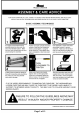
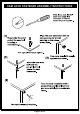
CAM LOCK FASTENER ASSEMBLY INSTRUCTIONS Page 5 of 13
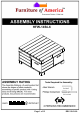
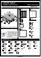
COFFEE TABLE ASSEMBLY INSTRUCTIONS MODEL # HFW-1454-6 please keep for future reference PARTS LIST A 1PC E 1PC H B 4PCS G B DIMENSIONS : 31.5"(W)*31.5"(D)18.
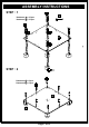
ASSEMBLY INSTRUCTIONS STEP : 1 7 Hardware 4 x 10 pcs Hardware 5 x 10 pcs E STEP : 2 Hardware 1 x 8 pcs Hardware 15 x 5 pcs E 15 Page 7 of 13
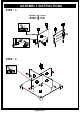
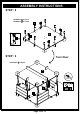
ASSEMBLY INSTRUCTIONS STEP : 3 Hardware 3 x 32 pcs Hardware 10 x 4 pcs Hardware 13 x 8 pcs Dowel hole B C 10 10 13 13 STEP : 4 Dowel hole C C E Page 8 of 13
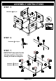
ASSEMBLY INSTRUCTIONS STEP : 5 Hardware 2 x 8 pcs B B STEP : 6 Hardware 3 x 10 pcs J F STEP : 7 IMPORTANT:Assemble Part #H with the position of the holes exactly as shown on diagram.
ASSEMBLY INSTRUCTIONS STEP : 8 Hardware 1 x 8 pcs Hardware 8 x 4 sets D STEP : 9 Turn Over Hardware 2 x 8 pcs D Page 10 of 13
ASSEMBLY INSTRUCTIONS STEP : 10 Hardware 1 x 6 pcs A STEP : 11 Hardware 3 x 8 pcs Page 11 of 13
ASSEMBLY INSTRUCTIONS STEP : 12 Hardware 2 x 6 pcs A Page 12 of 13
ASSEMBLY INSTRUCTIONS STEP : 13 Hardware 9 x 4 sets Hardware 11 x 8 pcs Hardware 12 x 16 pcs G STEP : 14 Hardware 12 x 24 pcs G 12 12 G ASSEMBLY IS COMPLETED Page 13 of 13 Make sure the unit is rested on a flat surface and does not feel loose or wobbly. If it does, double check all bolts/screws are secured and properly tightened.