HFW-1860C4 Page 1 of 14 REV.
Page 2 of 14
Page 3 of 14
Page 4 of 14
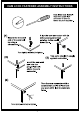
CAM LOCK FASTENER ASSEMBLY INSTRUCTIONS Page 5 of 14
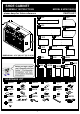
SHOE CABINET ASSEMBLY INSTRUCTIONS MODEL # HFW-1860C4 please keep for future reference PARTS LIST A 1PC C 1PC B 1PC D 1PC A J L F 1PC E 1PC M M D H 2PCS G 1PC DIMENSIONS : 47.2"(W)*15.7"(D)*33.4"(H) J 1PC I 2PCS N 2PCS K 1PC O 4PCS R 1PC L 1PC M 2PCS P 2PCS Q 1PC HARDWARE LIST 1 15PCS 2 15PCS 3 16PCS 4 1PC 5 7PCS 6 2SETS 2.2" 7 3SETS 8 2PCS 9 2PCS 10 4PCS 0.6" 0.5" 13 16PCS 14 3SETS 15 5SETS 16 8SETS 0.8" 11 20PCS 12 4PCS 0.5" 17 1PC 18 2SETS 0.
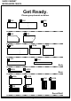
SHOE CABINET MODEL#HFW-1860C4 Get Ready. Please group boards as below.
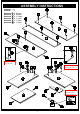
ASSEMBLY INSTRUCTIONS STEP : 1 Hardware 1 Hardware 3 Hardware 6 Hardware 8 Hardware 9 Hardware 10 x x x x x x 15 16 2 2 2 4 pcs pcs sets pcs pcs pcs B 6 6 8 F front 6 The magnets (#6) are facing outwards. 10 9 10 8 9 8 The front of all parts (#8) are facing outwards. D C G Use a dab of glue into dowel holes before inserting dowels (#3).
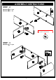
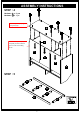
ASSEMBLY INSTRUCTIONS STEP : 2 Hardware 2 x 2 pcs Hardware 5 x 1 pc G F 5 F 2 Refer to page 5 on how to secure cam locks (#2) to cam bolts (#1).
ASSEMBLY INSTRUCTIONS STEP : 4 Hardware 5 x 6 pcs Hardware 17 x 1 pc 5 Grooves on panel (#B) aligns to back panels (#P). B Make sure back panels (#P) are completely flushed within the grooves of the surrounding panels.
ASSEMBLY INSTRUCTIONS STEP : 6 Hardware 2 x 6 pcs B N N STEP : 7 Hardware 19 x 6 pcs 19 19 Slightly hammer in the floor protectors (#19) to the bottom of the product.
ASSEMBLY INSTRUCTIONS STEP : 8 Hardware 2 x 3 pcs Hardware 13 x 16 pcs Hardware 14 x 3 sets Attach pins (#13) to the desired height of the shelves (#H,#I). R G 14 13 C 13 B H 13 14 13 H D I finish I STEP : 9 Hardware 7 x 3 sets Hardware 14 x 3 sets Hardware 15 x 3 sets 7 Attach the push up door pin telescopics (#14) to the following holes.
ASSEMBLY INSTRUCTIONS STEP : 10 2) Slide the doors (#L,M) to the top holes of panel (#F). F 1) Insert the bottom door pins of the doors (#L,M) to the bottom holes of panel (#B). B M M STEP : 11 Align hinges (#12) to the holes of the panels (#J,K), then secure by using screws (#11).
ASSEMBLY INSTRUCTIONS 1) Align hinges (#12) to the holes of the product as shown in the picture, then secure by using screws (#11). STEP : 12 Hardware 11 x 12 pcs F 11 11 J 11 11 11 11 11 11 J 2) Align hinges (#9) to the holes fo the panels (#J,K), then secure by using screws (#11). For safety reason, this item has been supplied with wall straps. We highly recommend securing the item to the wall using the supplied hardware and straps to prevent tip-over resulting in damages and/or injuries.