
User Manual

IM-DV5700-Rev1.0 - PAGE 3
21
43
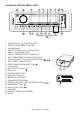
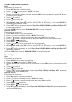
182.6mm
51mm
194.6mm
32.7mm
9.15mm
231
54
182.6mm
51mm
194.6mm
32.7mm
9.15mm
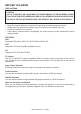
INSTALLATION GUIDE
Location
• Chooseamountinglocationawayfromhumidareas,watersources,appliancesoranyequipment
thatcanradiateheat.
• Selectanareaonawallorcabinetwhichisfreefromcable,fuelorbrakelinesandensurethatarea
behindthewallmountstereohasaventholeorifitisanenclosedboxandhasadequateroom
aroundtherearoftheunitforcooling.
• Ensurewhenthestereoismountedinthecutoutthatthewiresattherearoftheunitarenotpressed
againsttheheatsink.
Installing the unit
• Beforenallyinstallingtheunit,connectthewiringtemporarilyandmakesuretheunitandtheunit
andthesystemworkproperly.
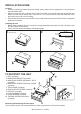
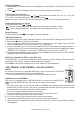
• Fixtheunitwithscrewaccordingtofollowingdiagram.
TO SUPPORT THE UNIT
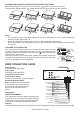
Detaching and attaching the front panel
Thefrontpanelofthisunitcanbedetachedinordertopreventtheunitfrombeingstolen.
Releasescrew
Recommended
cutout
4
1
5
7
9
6
8
7
8
9
10
8
9
2
3
4
2
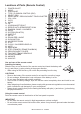
1.UNIT(included)
2.MOUNTINGBRACKET(included)
3.MOUNTINGSCREWCM5X8mmx4PCS
(included)
4.MOUNTINGSCREWPA5X16mmx4PCS
(included)
5.TRIMCOVER(included)
6.REARSUPPORTSTRAP(included)
7.HEXNUT(included)
8.LOCKWASHER(included)
9.PLAINWASHER(included)
10.TAPPINGSCREWPA5X16mm
(included)