
Installation Manual


APPENDIX 2 DIGITAL INTERFACE
AP-3
Transmission intervals
Load requirements as listener
Isolation: Provided
Input Impedance: Input Impedance: 110 ohms (130K ohms without jumper plug)
Max. Voltage: ±14 V to GNDiso
Threshold: ±0.2 V (A-B)
Output drive capability
Differential driver output
R=50 ohm 2 v min.
R=27 ohm 1.5 V min.
Driver short-circuit current
60 mA min. 150 mA max.
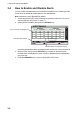
Data transmission
Data is transmitted in serial asynchronous form in accordance with the standard referenced in 2.1
of IEC 61162-1/2. The first bit is a start bit and is followed by data bits, least-significant-bit as il-
lustrated below.
The following parameters are used:
Baud rate: 38.4 Kbps /4800 bps
Data bits: 8 (D7 = 0), parity none
Stop bits: 1
Sentence Interval Sentence Interval
ABK With each event ACA When requested, or with each
event
ACS Transmitted after ACA ALC 30 seconds
ALF When requested, or with each
event
ALR 30 seconds
ARC With each event EPV When requested, or with each
event
HBT 50 seconds LR1 With each event
LR2 With each event LR3 With each event
LRF With each event LRI With each event
NAK With each event PIWWIVD When requested, or with each
event
PIWWSPR When requested, or with each
event
PIWWSSD When requested, or with each
event
PIWWVSD When requested, or with each
event
SSD When requested, or with each
event
TRL When requested, or with each
event
TXT When requested, or with each
event
VDM With each event VDO 1 second or with each event
VER When requested, or with each
event, or powered on
VSD When requested, or with each
event
D0 D1 D2 D3 D4 D5 D6 D7
Start
bit
Stop
bit
Data bits
IEC61162-1:Edition 4.0 2010-11
IEC61162-2:First Edition 1998-09
IEC61162-450:Edition 1.0 2011-06