MARINE RADAR/ARPA FAR-2117/2127/2817/2827 FAR-2117-BB/2127-BB Installation Manual Comply with MSC.192(79) TABLE OF CONTENTS 3.7 Dual Radar Display (non IMO-type only) ..................3-16 SAFETY IINSTRUCTIONS ..................... i 4. INSTALLING OPTIONAL EQUIPMENT LISTS...............................iii EQUIPMENT................................ 4-1 SYSTEM CONFIGURATION .................vi 4.1 Gyro Converter GC-10 .................4-1 1. MOUNTING..................................... 1-1 4.
The paper used in this manual is elemental chlorine free. ・FURUNO Authorized Distributor/Dealer 9‑52 Ashihara‑cho, Nishinomiya, 662‑8580, JAPAN Telephone : +81‑(0)798‑65‑2111 Fax : +81‑(0)798‑65‑4200 All rights reserved. Printed in Japan A : JAN . 2004 K1 : FEB. 25, 2011 Pub. No.
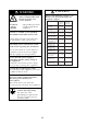
SAFETY INSTRUCTIONS The operator and installer must read the applicable safety instructions before attempting to install or operate the equipment. DANGER Indicates a potentially hazardous situation which, if not avoided, will result in death or serious injury. WARNING Indicates a potentially hazardous situation which, if not avoided, could result in death or serious injury. CAUTION Indicates a potentially hazardous situation which, if not avoided, can result in minor or moderate injury.
CAUTION WARNING Do not open the equipment unless totally familiar with electrical circuits and service manual. ELECTRICAL SHOCK HAZARD Observe the following compass safe distances to prevent deviation of a magnetic compass: Standard compass Only qualified personnel should work inside the equipment. Antenna Unit (12 kw) Antenna Unit (25 kw) Monitor Unit (MU-201CR) Monitor Unit (MU-231CR) Construct a suitable service platform from which to install the antenna unit.
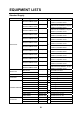
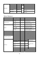
EQUIPMENT LISTS Standard Supply Name Type Code No.
Spare Parts SP03-12501 008-485-360 SP03-14404 008-535-910 1 For antenna unit For processor unit 100 VAC set 1 SP03-14405 008-535-920 SP03-14406 008-535-930 For processor unit 220 VAC set For processor unit 24 VDC set SP03-14401 008-535-990 For monitor unit AC set SP03-03900 000-081-063 SP03-14402 008-536-000 For monitor unit, DC set, 1 MU-201CR For monitor unit, DC set, MU-231CR Optional Equipment Name Type Code No. Remarks Gyro Converter GC-10-2 000-080-440 See chapter 4.
FR-FTPC-CY OP03-28900 000-082-658 OP03-28910 000-082-629 OP03-28920 000-082-660 FP03-09820 008-535-560 Hanger assy. for MU-201CR FP03-09830 008-536-020 Hanger assy.
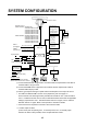
SYSTEM CONFIGURATION Performance Monitor ANTENNA UNIT FAR-2117/2817: XN12AF-RSB-096-078A XN12AF-RSB-097-078A XN20AF-RSB-096-078A XN20AF-RSB-097-078A XN24AF-RSB-096-078A XN24AF-RSB-097-078A FAR-2127/2827: XN12AF-RSB-096-079A XN12AF-RSB-097-079A XN20AF-RSB-096-079A XN20AF-RSB-097-079A XN24AF-RSB-096-079A XN24AF-RSB-097-079A EPFS 1) (Navigator) SDME 2) (Speed Log) IEC-61162 Serial Data (Input/Output) * MONITOR UNIT MU-201CR (CAT1) (FAR-2117/2127) or MU-231CR (CAT2) (FAR-2817/2827) JB ** CONTROL UNIT RCU-0
1. MOUNTING NOTICE Do not apply paint, anti-corrosive sealant or contact spray to coating or plastic parts of the equipment. Those items contain organic solvents that can damage coating and plastic parts, especially plastic connectors. 1.1 Antenna Unit Mounting considerations • The antenna unit is generally installed either on top of the wheelhouse, on the radar mast, or on a suitable platform. Locate the antenna unit in an elevated position to permit maximum target visibility.
1. MOUNTING • Install the antenna unit away from interfering high-power energy sources and other transmitting radio antenna. • Keep the lower edge of the antenna unit above the safety rail by 500 mm or more. • Two antenna units should be mounted as below: more than 20 more than 1 m • No funnel, mast or derrick should be within the vertical beamwidth of the antenna unit in the bow direction, especially zero degrees ±5°, to prevent blind sectors and false echoes on the radar picture.
1. MOUNTING Assembling the antenna unit The antenna unit consists of the antenna radiator and the antenna unit chassis, and they are packed separately. Fasten the antenna radiator to the antenna unit chassis as follows: 1. For the XN20AF, XN24AF, attach two guide pins to the underside of the antenna radiator. 2. Remove the waveguide cap from the radiator bracket. The cap may be discarded. 3. Coat the waveguide flange with anticorrosive sealant as shown below.
1. MOUNTING Antenna radiator Waveguide Radiator bracket Guide pin (XN20AF, XN24AF only) O-ring Hex bolt (M8x40), 8 pcs. (XN20AF, XN24AF) Hex. bolt (M8x35), 8 pcs. Flat washer Spring washer (XN12AF) Fastening the radiator to the radiator bracket Fastening the antenna unit to the mounting platform The antenna unit may be assembled before hoisting it to the mounting platform. However, do not lift the antenna unit by the radiator. Always hold the unit by its housing.
1. MOUNTING 4. Place the antenna unit on the rubber mat, orienting the unit so the bow mark on its base is facing the ship’s bow. Ground terminal Rubber mat Bow mark Antenna unit, front view 5. Fasten the antenna unit to the mounting platform with M12x60 hex bolts, nuts, flat washers and seal washers. 6. Using hex bolt (M6x25), nut (M6) and flat washer (M6), establish the ground system on the mounting platform as shown below. The location should be within 340 mm of the ground terminal on the antenna unit.
1. MOUNTING 1.2 Monitor Unit The monitor unit can be flush mounted in a console panel, or mounted on a desktop using the optional accessories. Note: FAR-2117-BB/2127-BB have no monitor unit. Prepare a suitable monitor locally.
1. MOUNTING 4-φ8 FIXING HOLES 4-FIXING HOLES (96) 313±1 505 313±1 471 570±1 554 570 ±1 598 30 80 Monitor unit MU-231CR (For FAR-2817/2827) Flush mounting of monitor unit Panel hook Panel cover Fixing screw Attaching panel hook and panel cover Note: If you need to remove the monitor unit from the mounting panel, remove the four panel covers with your fingernail and use two panel hooks supplied as accessories to lift the monitor unit.
1. MOUNTING Desktop mounting Use the optional accessories to mount the monitor unit on a desktop. • For FAR-2117/2127: FP03-09820 (Code No.: 008-535-560) • For FAR-2817/2827: FP03-09830 (Code No.: 008-536-020) Contents of FP03-09820/09830 Name Type Code No. Qty Hanger L 03-163-1111 100-305-141 1 Hanger R 03-163-1112 100-305-181 1 03-163-1113 100-305-191 03-163-2071 100-305-371 Hole plug CP-30-HP-13 000-160-074-10 2 Plastic rivet KB-13 Rivet Black 000-570-276-10 4 Hex.
1. MOUNTING Hanger (L) M12 bolts for fixing (Dockyard supply) Hanger stay Hanger (R) Panel cover Plastic rivet Flat Washer M10 Spring Washer M10 Hex bolt (M6x25) Hex bolt M10x30 Hole plug Panel cover To remove this, insert fingernail in groove. Monitor Unit The hand grip is optionally available for the desktop mounting monitor unit. Wave washer Rosette washer Screw Handle Hood (option) When it is too bright in the daytime, use the optional hood to shade the screen.
1. MOUNTING 1. Desktop mounting: Fasten the fixing plates to the fixing holes with the hex head bolts (supplied). Flush mounting: Fasten the display unit to the mounting location, and then attach the fixing plates with four self-tapping screws. Hex head bolt Fixing plate Fixing hole 2. Attach the hood to the display unit (the hood is outside of the fixing plates). 3. Fasten the hood to the fixing plates with four screws supplied (M4x10). 1.
1. MOUNTING Fixing with KB fixing plate 1. Fix the KB fixing plate to the bottom of the control unit. 2. Attach cushions (three for RCU-014, two for RCU-015/016) to the bottom of the control unit as shown below. 3. Fix it to a desired location with self-tapping screws (local supply). KB fixing plate Cushion Side view for RCU-014/015/016 Fixing without KB fixing metal 1. Drill four mounting holes of 5 mm diameter referring to the outline drawing at the back of this manual. 2.
1. MOUNTING Flush mounting Use the optional flush mount kit FP03-09870 to mount the control unit RCU-014, RCU-015 and/or RCU016 to a console panel. Name: Flush mount kit Type: FP03-09870 Code No.: 008-535-630 No. Name Type Code No. Qty 1 Mount plate 03-163-7531 100-306-261 4 2 Hex nut M5 000-863-108 4 3 Wing screw M5x40 000-162-682-10 4 4 Pan head screw M4x12 000-163-192-10 4 1. Prepare a cutout in the mounting location as shown in the figure below.
1. MOUNTING To connect RCU-016 in series with RCU-014 1. Pass the cable derived from RCU-016. 2. Connect the connector of the cable to J502. 3. Clamp the copper part of the cable with the cable clamp.
1. MOUNTING To change the cable entry To change the cable entry from the side (default) to the bottom, modify the unit as shown below. Bottom of the unit Screw M3x8 2. Pull out the cable. Cable clamp 03-163-7804 3. Pass the cable from this hole. Screw M4x8 4. In here, clamp the copper part of the cable with the cable clamp removed at step1. J5 2 1 J5 2 4 1. Remove the cable clamp. J522: If you connect RCU-016 in series with RCU-015, plug in here.
1. MOUNTING 1.4 Processor Unit Mounting considerations When selecting a mounting location, keep in mind the following points: • Locate the processor unit away from heat sources because of heat that can build up inside the cabinet. • Locate the equipment away from places subject to water splash and rain. • Leave sufficient space at the sides and rear of the unit to facilitate maintenance. • A magnetic compass will be affected if the processor unit is placed too close to the magnetic compass.
1. MOUNTING This page is intentionally left blank.
2. WIRING Wiring consideration • To lessen the chance of picking up electrical interference, avoid where possible routing the signal cable near other onboard electrical equipment (radars, transmitting radio antennas, etc.) Also avoid running the cable in parallel with power cables. When crossing with other cable, the angle should be 90°to minimize the magnetic field coupling. • The signal cable run between the antenna and processor units is available in lengths of 15 m (standard), 30 m and 50 m.
2. WIRING 2.2 Antenna Unit NOTE The magnetron in the transceiver module will demagnetize if it contacts ferrous material. When dismounting the transceiver module, lay it on its side or on top of non-ferrous material as shown below. Transceiver module (magnetron inside) Non-ferrous block Height more than 5 cm 1. Open the rear cover of the antenna unit 2. Disconnect plugs P823, P803, P831 and P921. If the PM-31 is installed, also disconnect plug P911. 3.
2. WIRING Antenna unit, front view, cover removed 6. Fabricate the signal cable RW-9600 as shown below. a) Remove the outer vinyl sheath, by about 500 mm, then armor and inner sheath by about 470mm. b) Unravel the shield to expose the core wires. c) Trim each core wire (except coaxial wire) considering its location on the terminal board. d) Trim the shield leaving about 500 mm and attach crimp-on lug FV5.5-4 (yellow, I4). e) Remove insulation of each wire by about 6 mm.
2. WIRING 8. Nip the armor between two washers, and trim the excess armor from around washers. And then pass the shield between the clamping ring and the washer as shown below. Fasten the clamping ring with the screws. 4-M4x16 Clamping ring Washer Shield Rubber gasket (25B) Armor Signal cable entrance 9. Connect the signal cable to the terminal board TB801 and TB802 on the RFTB board 03P9349 by referring to the interconnection diagram. Keep “slack” in the coaxial wire to prevent breakage.
2. WIRING 11. Set the transceiver module to the antenna unit, push it in until it stops, and then tighten fixing bolts (4 pcs.). Connect plugs P823, P803, P831, P921 and J911 (if installed). Fasten the shield wire to the wing nut on the transceiver module. CAUTION Push in transceiver unit until it stops. Failure to do so may cause leakage of microwaves. Clamp for coaxial cable 03P9349 Connect coaxial cable here.
2. WIRING 2.3 Monitor Unit Two cables are terminated at the display unit: the signal cable from the processor unit (5 m or 10 m cable) and the power cable from the ship’s mains. The signal cable comes with a connector preattached to it for connection to the monitor unit. Fabricate the power cable as below. Use DPYC-2.5 (Japan Industry Standard) cable or the equivalent. Fabricating the power cable 1. 2. 3. 4. 5. Cut armor of the cable by 40 mm. Cut vinyl sheath by 35 mm.
2. WIRING 2.4 Processor Unit Four cables are terminated at the processor unit: the antenna unit cable, display unit cable, control unit cable and the power cable. Cables other than the power cable come with a connector preattached to them for connection to the processor unit. Fabricate the power cable as below. For the power cable, use DPYC-2.5 (Japan Industry Standard) cable for AC unit or DPYC-6 for DC unit, or the equivalent.
2. WIRING Connection of cables The power cable is connected to the terminal board on the rear panel and the signal cable from the monitor unit is connected to the DVI-D connector. Other cables are connected to the printed circuit board 03P9342. Power cable clamp Monitor unit Power cable terminal board * Network DVI-D monitor Remove the protection cover.
2. WIRING Location of connectors Open the processor unit as follows and the 03P9342 board appears.
2. WIRING Cable fabrication for the cables connected to the 03P9342 board x Signal cable RW-9600 (Between antenna unit and processor unit) Vinyl sheath Armor Shield 450 60 5 After exposing cores, wind shield around the armor. Vinyl tape 6 14 5 9 Coaxial cable Conductor Fold back shield. Clamp here by cable clamp. Coaxial cable x Other cables for optional units Use TTYCS-1 or TTYCS-4 (Japan standard cable) or equivalent. Armor φ = 16.3 mm Armor Sheath Sheath φ = 10.
2. WIRING Connection of Sub-display A conventional remote display and/or FAR-2107 series radar can be connected to J617 and J618 in the processor unit as a sub-display. However, the control for GAIN and STC are different depending on J617 and J618. Refer to the table to connect sub-displays. Port J617 Conventional remote display FAR-2107 series radar Overall gain Even if input video level is adjusted to 4 Vp-p, the gain is 8 db lower than that on the master radar.
2. WIRING 2.5 Changing AC Power Specification of Processor Unit To change AC power specification between 100 VAC and 220 VAC, add or remove jumper connector P108 on the PWR board 03P9339 and change the fuse on the processor unit according to ship’s mains as shown in the table below. The figures below and on the next page show the location of the fuse and the jumper connector on the PWR board. Also, adjustment of the overvoltage detection circuit is required.
2. WIRING J105 PWR board J106 (P)HV J104 J103 R21 (OVER) P108/J108 J101 AC FIL 87654321 Jumper connector (VH8P) How to adjust the overvoltage detection circuit: 1. Add or remove the jumper connector P108 and change the fuse. 2. Rotate R21 fully clockwise on the PWR board. 3. Connect a variable transformer between ship's mains and the input power terminal board TB-1 of the processor unit. 4. Adjust the variable transformer output (i.e., input voltage to the processor unit) as follows.
2. WIRING This page is intentionally left blank.
3. SETTING AND ADJUSTMENT 3.1 DIP Switch Setting The processor unit is shipped for model FAR-2117 or FAR-2127. If your model is FAR-2817/ 2827/2117-BB/2127-BB, change the DIP switch setting as follows. 1. Remove the top cover of the processor unit. 2. Open the SPU assembly block. Shield cover SPU assembly block SPU board 03P9337 DIP switch S1 3. Set the DIP switch S1 as follows.
3. SETTING AND ADJUSTMENT 3.2 Initializing Tuning 1. Transmit the radar on 48 nm range and rotate the GAIN knob to show 70-80 of the gain bar. 2. Roll the trackball to choose the MENU box at the right side of the screen and then push the left button. 3. Roll the wheel to choose 1 ECHO and then push the wheel.
3. SETTING AND ADJUSTMENT 3.3 Heading Alignment You have mounted the antenna unit facing straight ahead in the direction of the bow. Therefore, a small but conspicuous target dead ahead visually should appear on the heading line (zero degrees). In practice, you will probably observe some small bearing error on the display because of the difficulty in achieving accurate initial positioning of the antenna unit. The following adjustment will compensate for this error.
3. SETTING AND ADJUSTMENT 3. Read the target bearing. 4. Measure the bearing of the stationary target on the navigation chart and calculate the difference between actual bearing and apparent bearing on the radar screen. 5. Press the [MENU] key to show the main menu. 6. While pressing and holding down the [HL OFF] key, press the [MENU] key five times. 7. Press the [0] key to show the [INITIALIZE] menu.
3. SETTING AND ADJUSTMENT How to Access the Installation Mode with the RCU-015 Trackball Style Controller 1. By using the trackball, move the pointer until it highlights the MENU box as shown. DO NOT CLICK the menu box, just leave the arrow over the menu. 2. Press and hold down the F1 key. Keep it held down during the next step. 3. Then, click on the right controller button 5 times. You should hear a “triple Beep” on the fifth press. The INITIALIZE menu will appear.
3. SETTING AND ADJUSTMENT 3.4 Adjustment Sweep Timing Sweep timing differs with respect to the length of the signal cable between the antenna unit and the processor unit. Adjust sweep timing at installation to prevent the following symptoms: • The echo of a “straight” target (for example, pier), on the 0.25 m range, will appear on the display as being pulled inward or pushed outward. See Figure below. • The range of target echoes will also be incorrectly shown.
3. SETTING AND ADJUSTMENT 3.5 Suppressing Main Bang If main bang appears at the screen center, suppress it as follows. 1. 2. 3. 4. Transmit the radar on a long range and then wait ten minutes. Adjust gain to show a slight amount of noise on the display. Select the 0.25 nm range. Adjust sea clutter control to suppress sea clutter. Press [5] key to choose the MBS on the [ECHO ADJ] menu. [ECHO ADJ] 1 BACK 2 CABLE ATT ADJ AUTO/MANUAL 30 3 HD ALIGN 000.0° 4 TIMING ADJ 0 5 MBS 0 6 DEFAULT ANT HEIGHT 5/7.
3. SETTING AND ADJUSTMENT 3.6 Other Settings ECHO menu setting Open the ECHO ADJ menu as described on page 3-3 and 3-4. [ECHO ADJ] 1 BACK 2 CABLE ATT ADJ AUTO/MANUAL 30 3 HD ALIGN 000.0° 4 TIMING ADJ 0 5 MBS 0 6 DEFAULT ANT HEIGHT 5/7.5/10/15/20/ 25/30/35/40/45/ more 50 m 7 NEAR STC CURVE 2/2.5/3/3.5/4.2 8 MID STC CURVE 3/4/5/6 9 FAR STC CURVE 6/7/8 0 RING SUPPRESSION 0 To close the menu, press the [MENU] key.
3. SETTING AND ADJUSTMENT Scanner setting 1. Open the INITIALIZE menu described on page 3-2. 2. Press [3] key to open the SCANNER menu. [SCANNER] 1 BACK 2 BLIND SECTOR 1 START 000° ANGLE 000° 3 BLIND SECTOR 2 START 000° ANGLE 000° 4 ANT REVOLUTION LO/HI/AUTO 5 ANT SW OFF/ON/EXT 6 ANT STOPPED STBY/TX 7 M SPEC OFF/ON 8 BB TYPE NORMAL/BB 9 [DUAL RADAR]* Note 1: Set the blind sector as minimum as possible. Note 2: Do not set the blind sector in the bow direction.
3. SETTING AND ADJUSTMENT INSTALLATION menu setting Open the INSTALLATION menu by pressing [4] key on the INITIALIZE menu. [INSTALLATION] 1 BACK 2 RADAR* MAIN/SUB 3 RANGE UNIT ** NM/SM/km/kyd 4 RADAR NO*** 1/2/3/4/5/6/7/8 5 RADAR POSN FORE/MAIN TOP/ MAIN 2ND/MAIN 3RD/ AFT/PORT/ STAR BOARD 6 MODEL 6/12/25 UP/25 DOWN/ 50/30 UP/30 DOWN/60 7 TYPE IMO/A/B/C/W 8 ON TIME XXXXXXX.X H 9 TX TIME XXXXXXX.X H 0 PM GAIN ADJ 0 *: Cannot be selected. **: non IMO-type only. ***: No.1-4: with antenna unit No.
3. SETTING AND ADJUSTMENT TYPE Choose type of radar: IMO, A, B, C, or W. ON TIME and TX TIME These items show number of hours the radar has been turned on and transmitted, respectively. Value can be changed; for example, after replacing magnetron TX Time can be reset to 0. PM GAIN ADJ Note: If you install the Performance Monitor PM-31 at field, see section 4.4 on page 4-16. When you choose this item, the radar setting changes as follows.
3. SETTING AND ADJUSTMENT OWN SHIP INFO menu setting Open the OWN SHIP INFO menu by pressing the [5] key on the INITIALIZE menu. [OWN SHIP INFO] 1 BACK 2 LENGTH/WIDTH LENGTH 100 m WIDTH 50 m 3 SCANNER POSN BOW 0 m PORT 0 m 4 GPS1 ANT POSN BOW 0 m PORT 0 m 5 GPS2 ANT POSN BOW 0 m LEFT 0 m 6 CONNING POSN BOW 0 m PORT 0 m LENGTH/WIDTH and SCANNER POSN To inscribe own ship shape on the screen when you choose it on the menu, enter length and width of the ship and antenna position from the bow and left sides.
3. SETTING AND ADJUSTMENT TT PRESET menu setting Open the TT PRESET menu by pressing [6] key on the INITIALIZE menu.
3. SETTING AND ADJUSTMENT TT W/O GYRO (Not on IMO radar) If a gyrocompass is not connected, choose the TT function, ON(working) or OFF (no working). LAND SIZE Set the land size in units of 100 m. The setting range is 100 to 3000 m. ANT SELECT Set the antenna radiator type of your radar. AUTO ACQ CORRE Set the correlation count of automatic acquisition. The setting range is 3 to 10. AUTO ACQ WEED Set the cancel count of automatic acquisition. The setting range is 1 to 5.
3. SETTING AND ADJUSTMENT OTHER menu setting Open the OTHER menu by pressing [8] key on the INITIALIZE menu. [OTHERS] 1 2 3 4 5 BACK DEMO ECHO OFF/EG/TT-TEST/PC EAV W/O GYRO OFF/ON TT CATEGORY SELECT CAT1/CAT2 3 INS OFF/SERIAL/LAN EAV w/o GYRO If a gyrocompass is not connected, choose the echo average function, ON (working) or OFF (no working). TT CATEGORY SELECT Choose CAT1 or CAT2•3 depending on your ship’s size.
3. SETTING AND ADJUSTMENT 3.7 Dual Radar Display (non IMO-type only) The image from both X-band and S-band radars may be shown together on one radar display. This allows you to take advantage of the best characteristics each type of radar has to offer. Two display formats are available, mixed and combine, and you may select desired format from the menu.
3. SETTING AND ADJUSTMENT Note 2: In the dual radar display, a guard zone set on the main radar is also accommodated on the external radar. When the position of the antennas for the main and external radars is different and the No. 2 guard zone is set on a close-in range, the on-screen guard zone may be shifted slightly from both the main radar antenna reference and external radar antenna reference. Accordingly, on the dual radar display, the actual guard zone area may be shifted slightly.
3. SETTING AND ADJUSTMENT 1. Push the right button four times to close the menu. Note 1: The dual radar function becomes inoperative when the external radar is turned off, set to stand-by, or set as sub display. When this happens, the buzzer sounds and the message "EXT RADAR STBY" (power off, stand-by only) appears. Note 2: The dual radar display is inoperative on the stern-up and shuttle ferry modes. Note 3: Some functions of the external radar image, listed below, may be adjusted from the main radar.
3. SETTING AND ADJUSTMENT 3.7.2 Specifying Sector Width and Length When 2 DUAL RADAR in the DUAL RADAR menu is set for "COMBINE", specify the width and length of the sector from the external radar to display on own radar. 1. Open the INITIALIZE menu. 2. Press the [3] key to show the SCANNER menu. 3. Select 9 [DUAL RADAR] and push the left button. 4. Select 3 COMBINE MODE and push the left button. 5. Select OWN or EXT and push the left button.
3. SETTING AND ADJUSTMENT 7. Use the scrollwheel to set START and ANGLE, referring to the description and example below. Spin the scrollwheel to set and push it to confirm. A solid green line marks the dual radar display area. • START: Start point of the sector (in degrees, 000-359) • ANGLE: Width of the sector (in degrees, 000-359) In the example below, START is 130° and ANGLE is 100°. Width of sector ANGLE (Example: 100°) START (Example: 130°) 8. Select 5 COMBINE RANGE and push the left button. 9.
3. SETTING AND ADJUSTMENT 3.7.3 Choosing External Radar (image source) Select the external radar to use in the dual radar display. 1. Open the INITIALIZE menu. 2. Press the [3] key to show the SCANNER menu. 3. Select 9 [DUAL RADAR] and push the left button. [DUAL RADAR] 1 BACK 2 DUAL RADAR OFF/MIX/COMBINE 3 COMBINE MODE* OWN/EXT 4 COMBINE SECTOR* START 000° ANGLE 000° 5 COMBINE RANGE* START 00.00NM LENGTH 00.00NM 6 EXT RADAR 1/2/3/4 * Shown when 2 DUAL RADAR is set for other than "MIX". 4.
3. SETTING AND ADJUSTMENT This page is intentionally left blank.
4. INSTALLING OPTIONAL EQUIPMENT 4.1 Gyro Converter GC-10 The Gyro Converter GC-10, incorporated inside the processor unit, converts analog gyrocompass reading into digital coded bearing data for display on the radar screen. This section explains how to install the GC-10 (mainly consisting of the GYRO CONVERTER board) and set it up according to gyrocompass connected.
4. INSTALLING OPTIONAL EQUIPMENT 2. Fasten the GYRO CONVERTER board in the processor unit with five washer head screws and male connector 231-607/019-FUR (called J602) with two screws. Screw M3x8 5 pcs GYRO CONVERTER board 64P1106A Screw M2.6x10 2 pcs 1 7 Connector (231) 231-107/026-FUR 7 1 Connector (231) 231-607/019-FUR Attaching GYRO CONVERTER board in the processor unit 3. Connect the GYRO CONVERTER board and the 03P9342 board with connector assemblies 03-2088 and 03-2091.
4. INSTALLING OPTIONAL EQUIPMENT 4. Connect the GYRO CONVERTER board and J602 with two connector assemblies 03-2089 and 03-2090. Wiring for WAGO connector Press downward. Terminal opener Connection for J602 J602 P608 1 2 3 4 7 6 5 4 3 2 1 PPL BLU GRN YEL ORG From J5 RED BRN YEL ORG RED BRN WAGO connector Twist Wire Procedures 1. Twist the cores 2. Press the terminal opener downward. 3. Insert the wire to hole. 4. Remove the terminal opener. 5. Pull the wire to confirm that it is secure.
4. INSTALLING OPTIONAL EQUIPMENT 5. Confirm gyrocompass specifications and set up the DIP switches and jumper wires on the GYRO CONVERTER board according to gyrocompass connected: x Setting jumper wires and DIP switches by gyrocompass specifications: page 4-5 x Setting jumper wires and DIP switches by make and model of gyrocompass: page 4-7 x Location of jumper wires and DIP switches: page 4-8 6.
4. INSTALLING OPTIONAL EQUIPMENT Connection of external power supply An external power supply is necessary when the repeater signal is step-by-step type and the step voltage is below 20 V or output voltage is less than 5 W. 1. Cut jumper wire JP1 on the GYRO CONVERTER board when an external power supply is used. 2. Connect gyro cable and power cable as shown below.
4.
4.
4.
4. INSTALLING OPTIONAL EQUIPMENT 4.2 Memory Card Interface Unit Mounting considerations When selecting a mounting location, keep in mind the following points: x Locate the memory card interface unit away from heat sources because of heat that can build up inside the cabinet. x Locate the unit away from places subject to water splash and rain. x Leave sufficient space at the sides and rear of the unit to facilitate maintenance.
4. INSTALLING OPTIONAL EQUIPMENT Desktop mount For desktop mount, the optional desktop mount kit FP03-10201 is required. Refer to the end of this manual. 1. Fix the mounting bracket 19-023-3081 on the unit with four screws. 2. Mount the above assembly on a desktop with four tapping screws. Console mount For console mount, the optional console mount kit FP03-10202 is required. Refer to the end of this manual. 1. Fix the mounting bracket 19-023-3091 on the unit with four screws. 2.
4. INSTALLING OPTIONAL EQUIPMENT No.1 J614 Processor unit NETWORK MJ-A3SPF0015-100 (10 m) Memory card IF unit 12 VDC FR-FTPC-CY (10/20/30 m) (straight) two mini-cards NETWORK FR-FTPC-CY (10/20/30 m) (straight) No.2 Processor unit No.3 Processor unit No.
4. INSTALLING OPTIONAL EQUIPMENT 4.3 DVI-RGB Conversion Kit (for VDR connection) This information provides the procedure necessary for the installation of the DVI-RGB conversion kit. This kit is installed in the processor unit to enable connection of a VDR (Voyage Data Recorder) or RGB monitor to record radar pictures into a VDR. When changing the D-sub 15P of the RGB cable to the BNC connector, use the BNC connector converter described on page 4-17.
4. INSTALLING OPTIONAL EQUIPMENT 1. Remove the top cover and open the upper part of the processor unit. DVI-D port (Connect DVI cable at step 13) Processor unit 2. Fix the 03P9229B board (RGB-BUFF) with four screws. (See the figure below.) 3. Attach the connector assemblies to J1 and J3 on the 03P9229B board as follows. J1㧦13-pin connector of the connector assembly 03-2094 J3㧦3-pin connector of the connector assembly 03-2093 4.
4. INSTALLING OPTIONAL EQUIPMENT DVI-RGB Conversion board J3 (Connect DVI cable at step 10.) J9 J4 Fixing the DVI-RGB conversion board 6. Attach the 10-pin connector from J1 on the 03P9229B board to J9 on the DVI-RGB board. 7. Attach the connector assembly 03-2092 to J4 on the DVI-RGB conversion board. 8. Remove connector housing J615 from the 03P9342 board. Connect the cable from J3 on the 03P9229B board and the cable from J4 on the DVI-RGB conversion board to J615.
4. INSTALLING OPTIONAL EQUIPMENT 4.4 Performance Monitor PM-31 This kit is installed in the antenna unit of the FAR-2107/2807 series X-band radar to monitor radar performance. Name: Type: Code no.: Performance monitor PM-31 008-080-438 Name Ԙ SCANNER COVER ASSY. ԙ GREASE Ԛ SM-XH CONNECTOR ASSY.