OPERATOR'S MANUAL MARINE RADAR/ARPA MODEL FAR-28x7 Series FAR-21x7(-BB) Series Complies with IMO MSC.192(79) www.furuno.co.
IMPORTANT NOTICES General • The operator of this equipment must read and follow the descriptions in this manual. Wrong operation or maintenance can cancel the warranty or cause injury. • Do not copy any part of this manual without written permission from FURUNO. • If this manual is lost or worn, contact your dealer about replacement. • The contents of this manual and equipment specifications can change without notice.
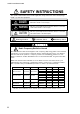
SAFETY INSTRUCTIONS SAFETY INSTRUCTIONS The operator and installer must read the applicable safety instructions before attempting to install or operate the equipment. DANGER Indicates a potentially hazardous situation which, if not avoided, will result in death or serious injury. WARNING Indicates a potentially hazardous situation which, if not avoided, could result in death or serious injury.
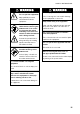
SAFETY INSTRUCTIONS WARNING ELECTRICAL SHOCK HAZARD WARNING Use the proper fuse. Do not open the equipment. Only qualified personnel should work inside the equipment. Turn off the radar power switch before servicing the antenna unit. Post a warning sign near the switch indicating it should not be turned on while the antenna unit is being serviced. Prevent the potential risk of being struck by the rotating antenna and exposure to RF radiation hazard.
SAFETY INSTRUCTIONS CAUTION WARNING No one navigational aid should be relied upon for the safety of vessel and crew. The navigator has the responsibility to check all aids available to confirm position. Electronic aids are not a substitute for basic navigational principles and common sense. • This TT automatically tracks automatically or manually acquired radar targets and calculates their courses and speeds, indicating them by vectors.
TABLE OF CONTENTS FOREWORD ........................................................................................................ xi PROGRAM NUMBER ......................................................................................... xv SYSTEM CONFIGURATION.............................................................................. xvi 1. RADAR OPERATION.................................................................................... 1-1 1.1 1.2 1.3 1.4 1.5 1.6 1.7 1.8 1.9 1.10 1.11 1.12 1.
TABLE OF CONTENTS 1.22 Measuring Range and Bearing Between Two Targets ...............................................1-38 1.23 Target Alarm ...............................................................................................................1-39 1.23.1 How to set a target alarm ................................................................................1-39 1.23.2 Acknowledging the target alarm ......................................................................1-40 1.23.
TABLE OF CONTENTS 1.39 1.40 1.41 1.42 1.43 1.44 Brilliance of Screen Data ........................................................................................... 1-75 Watch Alarm .............................................................................................................. 1-76 Nav Data ................................................................................................................... 1-77 Text Window .....................................................................
TABLE OF CONTENTS 3.6 Manual Acquisition .......................................................................................................3-7 3.6.1 Setting manual acquisition conditions ...............................................................3-7 3.6.2 Manually acquiring targets.................................................................................3-7 3.7 Lost Target ...................................................................................................................
TABLE OF CONTENTS 4.7 Target Data .................................................................................................................. 4-9 4.7.1 Basic target data ............................................................................................... 4-9 4.7.2 Detailed target data......................................................................................... 4-10 4.7.3 Removing a target data display ......................................................................
TABLE OF CONTENTS 5.10 5.11 5.12 5.13 5.14 5.9.5 Erasing track from the menu, on the screen....................................................5-16 5.9.6 Erasing track with the cursor ...........................................................................5-17 Waypoints ..................................................................................................................5-18 5.10.1 Entering waypoints ........................................................................................
FOREWORD A Word to the Owner of the FAR-28x7/FAR-21x7(-BB) Congratulations on your choice of the FURUNO FAR-28x7/FAR-21x7(-BB) Series Radar and TT. We are confident you will see why FURUNO has become synonymous with quality and reliability. For 60 years FURUNO Electric Company has enjoyed an enviable reputation for innovative and dependable marine electronics equipment. This dedication to excellence is furthered by our extensive global network of agents and dealers.
FOREWORD • TT, AIS, Radar Plotter and Interswitch supplied as standard. • Meets the requirements in IEC 62388 (Maritime navigation and radiocommunication equipment and systems - Shipborne radar - Performance requirements, methods of testing and required test results). • Meets the requirements in IMO MSC.192(79).
FOREWORD Radar Type and Function Availability This radar series is available in five specification types to meet the requirements of Authorities, and function availability depends on specification type. The table below shows those functions that have limited availability. This manual provides descriptions for all functions in this radar series, and we have endeavored to denote in the text those functions that have limited availability.
FOREWORD Specification type and function availability (con't) Function Trail Eraser Trails-Color Trails-Hide Trails-Long Trails-Narrow WPT marker IMO No No No No No No Type B A No No No No No Yes Yes Yes Yes Yes Yes Yes C Yes Yes Yes Yes Yes Yes W No Yes Yes Yes(12H/24H) Yes Yes Signal Processing Functions This radar has the signal processing functions described in the table below. All signal processing functions are set with the Picture feature. See section 1.35 for additional information.
PROGRAM NUMBER PC Board Program No. Version No. MAIN 035-9204 03.** (Merchant) RFC 035-9202 01.** KEY(REMOTE) 035-9203 01.** ARPA 035-9212 01.
SYSTEM CONFIGURATION See page xvii for detailed information about antenna units and radiators.
SYSTEM CONFIGURATION Antenna unit FAR-2117, FAR-2117-BB, FAR-2127, FAR-2127-BB, FAR-2827 RSB-096 (24 rpm) RSB-097 (42 rpm) FAR-2137S, FAR-2137S-BB RSB-098/099 (21/26 rpm, 200 VAC, 3ø, 50 Hz; 220 VAC, 3ø, 60 Hz; 380 VAC, 3ø, 50 Hz, 440 VAC, 3ø, 60 Hz) RSB-100/101/102 (45 rpm, 220 VAC, 3ø, 50/60 Hz(HSC); 440 VAC, 3ø, /60 Hz(HSC)) FAR-2827W RSB-103 (24 rpm, powered by processor unit) FAR-2837S Same as FAR-2137S FAR-2837SW RSB-104/105 (21/26 rpm, 200 VAC, 3ø, 50 Hz; 220 VAC, 3ø, 60 Hz; 380 VAC, 3ø, 50
SYSTEM CONFIGURATION Blackbox type FAR-2137S-BB FAR-2117-BB/2127-BB ANTENNA UNIT (Performance Monitor PM-51 built in FAR-2137S-BB) ANTENNA UNIT (Performance Monitor PM-31 built in FAR-2117-BB, FAR-2127-BB) VGA Monitor CONTROL UNIT RCU-014 (Keyboard) or RCU-015 (Trackball) POWER SUPPLY UNIT PSU-007 (For FAR-2137S-BB/2837S-BB) Control Unit RCU-016 (Remote) PROCESSOR UNIT RPU-013 Sub Display Alarm VDR External Monitor : Standard IEC-61162-1 Serial Data Navigator (INS, GPS, etc.
SYSTEM CONFIGURATION Console type RCN-001/RCN-002 FAR-2137S/2837S/2837SW FAR-2117/2127/2817/2827/2827W ANTENNA UNIT (Performance Monitor PM-51 built in) ANTENNA UNIT (Performance Monitor PM-31 built in) Waveguide (For FAR-2827W) Waveguide or Coax cable (For FAR-2837SW) TRANSCEIVER UNIT RTR-081A For FAR-2827W TRANSCEIVER UNIT RTR-082 For FAR-2837SW CONSOLE RCN-001/002 Alarm VDR POWER SUPPLY UNIT PSU-007 For FAR-2137S/2837S OR POWER SUPPLY UNIT PSU-011* (For FAR-2827W/2837SW) External Monitor IE
SYSTEM CONFIGURATION Console type RCN-003/RCN-004 FAR-2117/2127/2817/2827/2827W FAR-2137S/2837S/2837SW ANTENNA UNIT (Performance Monitor PM-51 built in) ANTENNA UNIT (Performance Monitor PM-31 built in) Waveguide (For FAR-2827W) Waveguide or Coax cable (For FAR-2837SW) TRANSCEIVER UNIT RTR-081A For FAR-2827W TRANSCEIVER UNIT RTR-082 For FAR-2837SW CONSOLE RCN-003/004 POWER SUPPLY UNIT PSU-007 For FAR-2137S/2837S OR POWER SUPPLY UNIT PSU-011* (For FAR-2827W/2837SW) * Russian flag only Alarm VDR Ex
1. RADAR OPERATION 1.1 Turning on the Power The [POWER] switch ( ) is located at the left corner of the control unit. Open the POWER switch cover and press the switch to turn on the radar system. To turn off the radar, press the switch again. The screen shows the bearing scale and digital timer approximately 30 seconds after power-on. The timer counts down three minutes of warm-up time. During this period the magnetron (transmitter tube) is warmed for transmission.
1. RADAR OPERATION The radar is initially set to previously used range and pulse length. Other settings such as brilliance levels, VRMs, EBLs and menu option selections are also set to previous settings. The [STBY/TX] key (or TX STBY box) toggles the radar between STBY and TRANSMIT status. The antenna stops in stand-by and rotates in transmit. The magnetron ages with time resulting in a reduction of output power.
1. RADAR OPERATION Control Unit Two types of control units are available: Control Unit RCU-014 (full keyboard) and Control Unit RCU-105 (palm control).
1. RADAR OPERATION Control description Control Description Control Unit RCU-014 (full keyboard) POWER Turns the system on and off. EBL and VRM rotary controls Adjust EBL and VRM, respectively. EBL ON, EBL OFF Turns the EBLs on and off, respectively. F1-F4 Execute menu short cut assigned. ALARM ACK Silences audio alarm. STBY TX Toggles between stand-by and transmit. BRILL Adjusts display brilliance. A/C RAIN Suppresses rain clutter. A/C SEA Suppresses sea clutter.
1. RADAR OPERATION 1.4 Main Menu You may access the MAIN menu from the full keyboard or by using the trackball. In later sections only the procedure for menu operation by trackball is given. Main menu operation by keyboard 1. Press the [MENU] key. The MAIN menu appears in the text area at the right side of the screen. [MAIN MENU] 1 2 3 4 5 6 7 8 9 [ECHO] [MARK] [ALARM] [TT AIS] [PLOTTER] [CARD] [NAV DATA] [NAV LINE WPT] [CUSTOMIZE TEST] Echo processing functions Mainly turns markers on/off.
1. RADAR OPERATION Main menu operation by trackball 1. Use the trackball to select the MENU box at the right side of the screen. The guidance box at the bottom right corner (see the illustration at the bottom of the next page for location) now reads "DISP MAIN MENU." 2. Push the left button to display the MAIN menu. [MAIN MENU] 1 2 3 4 5 6 7 8 9 [ECHO] [MARK] [ALARM] [TT AIS] [PLOTTER] [CARD] [NAV DATA] [NAV LINE WPT] [CUSTOMIZE TEST] Echo processing functions Mainly turns markers on/off.
1. RADAR OPERATION 1.5 Operation by the On-Screen Boxes All radar functions can be accessed by using the trackball alone. This is done by choosing the appropriate on-screen box with the trackball and operating the trackball module to select item and option. (See section 1.9 for location of all on-screen boxes.) On-screen boxes come in two varieties: Function selection and function selection w/pop-up menu.
1. RADAR OPERATION Trackball marker location and guidance box indication The trackball marker is either a cursor (+) or an arrow ( ) depending on whether it is within or outside the display area, respectively. Further, the indication in the guidance box changes according to trackball marker location. Guidance box reads "JUMP CURSOR / DISP MENU." Push the left button to choose the on-screen box closest to the arrow or push the right button to display the MAIN menu.
1. RADAR OPERATION 3. The pop-up menu attached to the MARK box is the MARK menu. To open the menu, push the right button. The menu opens in the text area at the right side of the screen. [MARK MENU] 1 ORIGIN MARK STAB GND/SEA 2 MARK KIND ORIGIN MARK(No. )/ ORIGIN MARK(SYM)/ MAP MARK/ WP 1~50/ WP 51~ 100/ WP 101~150/ WP 151~198/ OWN SHIP SHAPE 8 MARK POSN CURSOR/OS/L/L 00°000.00 N 000°000.
1. RADAR OPERATION 1.6 Cursor Menu Functions that require the use of the cursor, such as EBL offset and zoom, may be activated directly from the guidance box or from the CURSOR menu, either method with the cursor inside the effective display area. Below is the procedure for choosing a cursor-related function from the CURSOR menu. In later sections only the procedure for selection from the guidance box is given. 1. Put the cursor inside the effective display area. 2.
1. RADAR OPERATION 1.7 Monitor Brilliance The brilliance of the entire screen should be adjusted according to lighting conditions. Monitor brilliance should be adjusted before adjusting relative brilliance levels on the BRILL menu to be explained later. Note: The brilliance of a commercial monitor cannot be adjusted from the radar. See the owner’s manual of the commercial monitor for how to adjust its brilliance. By keyboard Operate the [BRILL] control on the control unit to adjust brilliance.
1. RADAR OPERATION 1.8 Display Modes This radar has the following display modes: • IMO, A type: Radar, Radar + Plotter, Anchor (Watch) • B, C, W type: Radar, Radar + Plotter, Plotter Select a display mode as below. Note that a display mode cannot be selected when the menu is open. 1. Use the trackball to place the arrow in the DISPLAY MODE box at the top of the screen. DISPLAY XX* * XX = display mode DISPLAY MODE box 2. Push the left button to select appropriate mode.
1. RADAR OPERATION 1.9 On-Screen Boxes and Markers Trial Maneuver (Elapsed time shown when trial maneuver is active.) Range, Bearing and TTG to cursor position Cursor Position Box PICTURE Box, Main Picture Settings PULSELENGTH Box ANTENNA Box PRESENTATION MODE Box RANGE Box REF POINT Setting DISPLAY MODE Box NM 6 /1 HEAD UP TB RM DISPLAY RADAR REF POINT ANT ANT 1 X-BAND PULSE S1 330 PICTURE4 340 350 000 SET and DRIFT Boxes GAIN Setting A/C SEA Setting A/C RAIN Setting TUNING Setting SET 000.
1. RADAR OPERATION HDG SPD SB COG SOG 9.9kn BT WT MAN 0.1kn 30.2°T 10.2.2kn GPS OS POSN Electronic Position-fixing System and position* Depth DGPS 34°40.00N 135°24.00E TRUE 15.4 m/s WIND 159.9°T DEPTH 22.30 m Depth Echogram (See section 1.41.) -30 20 10 Zoom display appears in nav data box when nav data is turned off. Heading is TRUE (variation-corrected gyro or magnetic heading) Speed data is LOG, MAN, etc., showing sensor and types. 242.2°T CURRENT TEMP WPT001 DATE 20 40 60 80 100 N W 2.
1. RADAR OPERATION 1.10 Tuning the Receiver 1.10.1 Choosing the tuning method The tuning method can be selected with the TUNE box at the top of the screen. 1. Select the TUNE box (TUNE AUTO or TUNE MAN) at the top of the screen. Tuning bar Place arrow inside box to adjust tuning, when TUNE MAN is selected. Tuning method (AUTO or MAN) TUNE AUTO Tuning level TUNE box 2. Push the left button or scrollwheel to display TUNE AUTO or TUNE MAN as appropriate. 3.
1. RADAR OPERATION 1.10.3 Automatic tuning Select automatic tuning following section 1.10.1. The TUNE box shows TUNE AUTO. 1.10.4 Manual tuning 1. Select the 48-mile range from the RANGE box. Push the left button to lower the range; the right button to raise the range. 2. Select manual tuning following the procedure in section 1.10.1. 3. Use the trackball to place the arrow on the tuning bar area in the TUNE box. 4. Roll the scrollwheel to adjust tuning.
1. RADAR OPERATION 1.12 Presentation Modes This radar has the following presentation modes: Relative Motion (RM) Head-up: Unstabilized Head-up TB: Head-up with compass-stabilized bearing scale (True Bearing) where the bearing scale rotates with the compass reading. Course-up: Compass-stabilized relative to ship’s orientation at the time of selecting course-up. North-up: Compass-stabilized with reference to north Stern-up: The radar image is rotated 180°.
1. RADAR OPERATION 1.12.2 Description of presentation modes Head-up mode The head-up mode is a display in which the line connecting own ship and the top of the display indicates own ship’s heading. The target pips are painted at their measured distances and in their directions relative to own ship’s heading. A short line on the bearing scale is the north marker indicating heading sensor north. A failure of the heading sensor input will cause the north marker to disappear and the readout to show ***.
1. RADAR OPERATION Head-up TB (True Bearing) mode Radar echoes are shown in the same way as in the head-up mode. The difference from normal head-up presentation lies in the orientation of the bearing scale. The bearing scale is heading sensor stabilized. That is, it rotates in accordance with the heading sensor signal, enabling you to know own ship’s heading at a glance. This mode is available when the radar is interfaced with a gyrocompass.
1. RADAR OPERATION Stern-up mode The stern-up mode rotates the head-up mode picture, relative and true bearings and display graphics 180°. This mode is useful on dual-radar tugboats when backing up; one radar shows head-up and another shows stern-up. To enable the stern-up mode, turn on STERN-UP on the 7 OPERATION menu.
1. RADAR OPERATION True motion mode Own ship and other moving objects move in accordance with their true courses and speed. In ground stabilized TM, all fixed targets, such as landmasses, appear as stationary echoes. In the sea stabilized TM without set and drift inputs, the landmass can move on the screen. Note that true motion is not available on the 72 nm (non-IMO type only) or 96 nm range scale.
1. RADAR OPERATION 1.13 Entering Own Ship's Speed The TT and azimuth stabilized presentation modes require own ship speed input and compass signal. The speed can be entered from a log (STW) or GPS (SOG) or manually on the menu. Note that FURUNO GPS Navigator GP-90 provides COG and SOG. 1.13.1 Automatic speed input by log or GPS navigator 1. Right-click the SPD box at the top right corner of the screen. [SPEED MENU] 1 SHIP SPEED LOG(BT)/LOG(WT)/ GPS/MANUAL/REF 2 MANUAL SPEED 0.
1. RADAR OPERATION • On the IMO type with AIS in use, LOG(WT), MANUAL and REF are shown in gray to indicate they are not available for selection. • A single-axis water log cannot measure speed when the wind is coming from the leeway direction. • If speed over the ground cannot be obtained in a deep area, select LOG(WT), turn on SET DRIFT and enter set and drift values. See section 3.12 for the procedure. 1.13.2 Manual speed input If the speed log is not working, enter speed manually as below.
1. RADAR OPERATION 1.15 Choosing a Pulselength The pulselength in use is displayed at the upper-left position of the screen using the indications shown in the table below. Label and pulselength X-band 10, 25 kW, S-band 30 kW Indication Pulselength (μs) S1 (Short pulse 1) 0.07 S2 (Short pulse 2) 0.15 M1 (Medium pulse 1) 0.3 M2 (Medium pulse 2) 0.5 M3 (Medium pulse 3) 0.7 L (Long pulse) 1.2 Appropriate pulselengths are preset to individual range scales and function keys.
1. RADAR OPERATION 2. Select 8 [PULSE]. [PULSE MENU] 1 BACK 2 0.5NM S1/S2 3 0.75NM S1/S2/M1 4 1.5NM S1/S2/M1 5 3NM S2/M1/M2/M3 6 6NM M1/M2/M3/L 7 12-24NM M2/M3/L PULSE menu 3. Select a range then push the left button. 4. Select pulselength desired then push the left button. 5. Push the right button twice to close the menu. 1.15.2 Changing pulselength 1. Use the trackball to select the PULSELENGTH box at the left side of the screen. The guidance box shows "PULSE SHORTER / PULSE LONGER.
1. RADAR OPERATION 1.16 Adjusting the Sensitivity The gain control adjusts the sensitivity of the receiver. The proper setting is such that the background noise is just visible on the screen. If you set up for too little sensitivity, weak echoes may be missed. On the other hand excessive sensitivity yields too much background noise; strong targets may be missed because of the poor contrast between desired echoes and the background noise on the display.
1. RADAR OPERATION 1.17 Reducing Sea Clutter Echoes from waves cover the central part of the display with random signals known as sea clutter. The higher the waves, and the higher the antenna above the water, the further the clutter extends. When sea clutter masks the picture, reduce it by the A/C SEA control, either manually or automatically. Note 1: When both sea clutter and rain clutter are reduced, the sensitivity is decreased more than when only one is adjusted. For that reason adjust them carefully.
1. RADAR OPERATION By trackball 1. Select SEA AUTO following the procedure in section 1.17.1. 2. Use the trackball to place the arrow in the A/C SEA level indicator at the top of the display. 3. While observing the A/C SEA level indicator, roll the scrollwheel downward to increase the A/C SEA or upward to decrease it. 100 levels (0-100) are available. 1.17.
1. RADAR OPERATION 1.18 Reducing Rain Clutter Use the AUTO RAIN and A/C RAIN to reduced rain clutter. AUTO RAIN reduces rain clutter in the picture and A/C RAIN reduces clutter picked up by the antenna. Note 1: When both sea clutter and rain clutter are reduced the sensitivity is decreased more than when only one is adjusted. For that reason adjust them carefully. Note 2: The echo average (see 1.27) is useful for reducing reflections from the sea surface.
1. RADAR OPERATION Note: The detection range is reduced when the A/C RAIN is used to show targets in rain. Generally, the amount of rain, TX pulse length and TX frequency are factors in determining how the detection range is affected. The figures shown below illustrate this occurrence.
1. RADAR OPERATION 1.19 Measuring Range The range to a target may be measured three ways: with the fixed range rings, with the cursor, or with the VRM. Use the fixed range rings to get an estimate of the range to a target. The rings are the concentric solid circles on the display. The number of rings is automatically set by the current range scale. The distance between the rings is the range ring interval, and the current interval appears at the upper-left position on the screen.
1. RADAR OPERATION 1.19.2 Measuring range by the variable range marker (VRM) There are two VRMs, No. 1 and No. 2, which appear as dashed rings so that you can distinguish them from the fixed range rings. The two VRMs can be distinguished from each other by the different lengths of their dashes; the dashes on the No. 2 VRM are longer. No. 1 VRM 330 340 350 000 010 020 030 320 Target blip 040 310 050 060 300 070 290 280 080 270 090 260 100 250 110 240 120 230 No.
1. RADAR OPERATION 1.19.3 VRM unit of measurement (B and C types) 1. 2. 3. 4. 5. 6. 1.19.4 Left-click the MENU box to open the menu. Select 2 [MARK]. Select 9 [EBL, VRM, CURSOR SET] then push the scrollwheel. Select VRM1 or VRM2 as appropriate and push the scrollwheel. Select unit of measurement desired then push the scrollwheel. Push the right button twice to close the menu. TTG to VRM indication You can show the TTG to VRMs as follows: 1. 2. 3. 4. 5. 6. Left-click the MENU box to open the menu.
1. RADAR OPERATION 1.20 Measuring Bearing Use the Electronic Bearing Lines (EBLs) to take bearings of targets. There are two EBLs, No. 1 and No. 2. Each EBL is a straight dashed line extending out from the own ship position up to the circumference of the radar picture. The two EBLs can be distinguished from each other by the different lengths of their dashes; the dashes on the No. 2 EBL are longer. Each EBL carries a range marker, or a short line crossing the EBL at right angles.
1. RADAR OPERATION No. 2 320 330 EBL 310 340 350 000 010 Target blip 020 030 040 050 060 300 070 290 280 080 270 090 260 100 Range markers on EBLs 250 240 110 120 230 130 140 220 210 150 200 EBL1 EBL2 No. 1 EBL 190 >128.0°T< 100.8°T 180 170 160 VRM1 VRM2 >10.2NM< 12.1NM Measuring bearing with EBLs 1.20.2 True or relative bearing The EBL readout is affixed by "R" (relative) if it is relative to own ship's heading, "T" (true) if it is referenced to the north.
1. RADAR OPERATION 1.21 Collision Assessment by Offset EBL The origin of the EBL can be placed anywhere with the trackball to enable measurement of range and bearing between any targets. This function is also useful for assessment of the potential risk of collision. It is possible to read CPA (Closest Point of Approach) by using a VRM as shown in (a) in the illustration on the next page.
1. RADAR OPERATION 330 340 350 000 010 020 330 030 320 A 020 030 060 070 A1 280 080 A1 050 290 070 290 040 A 300 060 280 010 310 050 300 350 000 320 040 310 340 080 270 090 270 090 260 100 260 100 250 110 240 EBL1 130 140 220 210 150 200 190 180 170 >150.3°T< 160 VRM1 (a) 110 240 120 230 No. 1 EBL 250 No. 1 EBL >3.85NM< EBL1 120 230 130 140 220 210 150 200 190 180 170 >138.2°T< 160 VRM1 (b) >3.
1. RADAR OPERATION 1.22 Measuring Range and Bearing Between Two Targets By keyboard 1. Press the [EBL OFFSET] key. Operate the trackball to place the origin of the No. 1 EBL, for example, on a target of interest (target 1 in the illustrated example). 2. Operate the EBL rotary control until the EBL passes through another target of interest (target 2). 3. Operate the VRM rotary control until the range marker on the EBL is on the inside edge of target 2.
1. RADAR OPERATION 1.23 Target Alarm The target alarm serves to alert the navigator to targets (ships, landmasses, etc.) entering a specific area, with audiovisual alarms. CAUTION • The alarm should not be relied upon as the sole means for detecting possible collision situations. • A/C SEA, A/C RAIN and GAIN controls should be properly adjusted to be sure the alarm system does not overlook target echoes. The target alarm zone has a fixed width of 0.
1. RADAR OPERATION Note 1: If you wish to create a target alarm zone having a 360-degree coverage around own ship, set point "B" in almost the same direction as point "A." Note 2: Two target alarm zones may be set. Note however that the 2nd target alarm zone is available only when the 1st target alarm zone is active. Note 3: When the target alarm zone is not within the range in use the indication UP RNG appears to the right of the ALARM box.
1. RADAR OPERATION 1.23.4 Target alarm attributes You may select the echo strength level that triggers the alarm, the condition that generates the alarm and the volume of the audio alarm as follows: 1. Left-click the MENU box to open the menu. 2. Select 3 [ALARM]. [ALARM] 1 BACK 2 TARGET ALARM MODE IN/OUT 3 TARGET ALARM LEVEL 1/2/3/4 4 WATCH ALARM OFF/6M/10M/ 12M/15M/20M 5 ALARM SOUND LEVEL OFF/LOW/MID/HIGH 6 [ALARM OUT1] 7 [ALARM OUT2] 8 [ALARM OUT3] 9 [ALARM OUT4] 0 [PRIMARY ALARM] ALARM menu 3.
1. RADAR OPERATION 1.24 Off-Centering the Display Own ship position, or sweep origin, can be displaced to expand the view field without switching to a larger range scale. The sweep origin can be off-centered to the cursor position, but not more than 75% of the range in use; if the cursor is set beyond 75% of the range scale, the sweep origin will be off-centered to the point of 75% of the limit. This feature is not available on the 96 nm range or in the true motion mode.
1. RADAR OPERATION 1.25 Interference Rejector Mutual radar interference may occur in the vicinity of another shipborne radar operating in the same frequency band. It is seen on the screen as a number of bright spikes either in irregular patterns or in the form of usually curved spoke-like dotted lines extending from the center to the edge of the picture. Activating the interference rejector circuit can reduce this type of interference. The interference rejector is a kind of signal correlation circuit.
1. RADAR OPERATION 1.27 Echo Averaging The echo averaging feature effectively reduces sea clutter. Echoes received from stable targets such as ships appear on the screen at almost the same position every rotation of the antenna. On the other hand, unstable echoes such as sea clutter appear at random positions. To distinguish real target echoes from sea clutter, echoes are averaged over successive picture frames.
1. RADAR OPERATION 1.28 Noise Rejector White noise may show itself on the screen as random "speckles" spread over the entire radar image. You can remove this noise as follows: 1. Right-click the PICTURE box at the left side of the screen to open the PICTURE menu. [PICTURE MENU] 1 INT REJECT OFF/1/2/3 2 ECHO STRETCH OFF/1/2/3 3 ECHO AVERAGE OFF/1/2/3 4 NOISE REJ OFF/ON 5 AUTO STC OFF/ON 6 AUTO RAIN OFF/1/2/3/4 7 VIDEO CONTRAST 1/2/3/4/ A/B/C 8 [PULSE] 9 [CONDITION] 0 DEFAULT NO/SAVE/USER/ FACTORY 2.
1. RADAR OPERATION 1.29 Wiper The wiper feature automatically reduces the brilliance of weak signals (noise, sea clutter, rain clutter, etc.) and unwanted signals such as radar interference to clear the picture of unwanted echoes. Its effect depends on the wiper setting used and whether each averaging is turned on or off, as described below.
1. RADAR OPERATION 1.30 Target Trails The trails of the radar echoes of targets may be displayed in the form of synthetic afterglow. Target trails are shown either relative or true and may be sea or ground stabilized. True motion trails require a compass signal, and position and speed data. 1.30.1 True or relative trails You may display echo trails in true or relative motion. Relative trails show relative movements between targets and own ship.
1. RADAR OPERATION 1.30.2 Trail time Trail time, the trail plotting interval, may be selected as follows: 1. Select the arrow in the TRAIL MODE box at the bottom right corner of the screen. * TRAIL ** * TRUE-S(or -G) or REL S: Sea stablized G: Ground stabilized ** Trail time setting TRAIL MODE box 2. Push the left button to select the trail time as below.
1. RADAR OPERATION 1.30.4 Saving, copying target trails By turning on the functions TRAIL RESTART and TRAIL COPY, you may continue painting target trails whenever the range scale is changed. The amount of range change determines how the radar paints trails. See the table below for details. Note however that if the previous range is restored within 10 seconds and the amount of range change is within 1/3, trails continue as before. If trails become difficult to view, you may delete them.
1. RADAR OPERATION The relationship between trail restart and trail copy depends on their status, as shown in the table below. 1.30.5 Trail restart Trail copy Trail status ON ON Range changed while trail is ON: Trails continue on targets within previous range. ON OFF Range changed while trail is ON: Trails within the previous range are erased then trails are restarted. OFF OFF/ON • Range changed while trail is ON: New trails not initiated. (Trails from previous range are stored in memory.
1. RADAR OPERATION 1.30.7 Longer trails (B, C and W types) In addition to the trail times mentioned in section 1.30.2, you may also extend trails 12 ,24 or 48 hours. 1. Right-click the TRAIL MODE box to display the TRAIL menu. 2. Select 8 TRAIL LENGTH. 3. Select NORMAL, 12H, 24H or 48H as appropriate. Note: 48H not available with W-type. NORMAL: Trails are extended according to the setting made on the TRAIL MODE box. 12H: Extend trails for 12 hours. 24H: Extend trails for 24 hours.
1. RADAR OPERATION 1.30.11 Preventing sea clutter in true trails You can prevent the display of sea clutter in true trails about your ship to clear the radar picture. Your ship's trails can also be shown or hidden. 1. Right-click the TRAIL MODE box to show the TRAIL menu. 2. Select 7 OS TRAIL and push the left button. 3. Roll the scrollwheel to select OFF, 1 or 2 as appropriate, referring to the table below. Option OFF 1 2 Show own ship's trail No Yes No Prevent sea clutter in true trails No Yes Yes 4.
1. RADAR OPERATION 1.31.2 Adjusting PI line orientation, PI line interval 1. If not already displayed, show a PI line, referring to section 1.31.1. 2. Use the trackball to place the arrow in PI 1 ON the PI line orientation box. PI line orientation 3. Roll the scrollwheel to adjust the PI 032.0°T PI line interval line orientation, between 5.60NM 000.0-359.9(°T). Enter a negative value to move the PI line to the opposite side of the PI line passing through the own ship position. 4.
1. RADAR OPERATION 1.31.4 Maximum number of PI lines to display The maximum number of PI lines to display may be selected from 1, 2, 3 or 6 lines as below. The actual number of lines visible may be less depending on line interval. For the W specification radar, you may specify the number of lines for two sets of PI lines – the menu displays 4 PI LINE1 and 5 PI LINE2. 1. 2. 3. 4. 5. 6. 1.31.5 Left-click the MENU box to open the menu. Select 2 [MARK] to open the MARK menu. Select 4 [PI LINE].
1. RADAR OPERATION 1.32 Origin Mark You can mark any prominent target or a point of particular interest using the origin mark feature. Twenty origin marks may be entered: 10 standard origin marks (with number) and one each of the 10 symbol origin marks. The marks may be geographically fixed (ground stabilized) or sea stabilized. To display the origin marks, heading signal and own ship position data are required. 1.32.1 Entering origin marks 1.
1. RADAR OPERATION 7. With the cursor choosing the MARK box, Select mark number desired ("ORIGIN MARK(No.)" selected at step 4) or origin mark symbol ("ORIGIN MARK(SYM)" selected at step 4) then push the left button. The following origin marks are available. Origin mark (symbols) 8. Push the left button again. The cursor jumps into the effective display area and the guidance box now reads "MARK / EXIT." 9. Use the trackball to put the cursor on the location desired. 10.
1. RADAR OPERATION 1.32.2 Origin mark stabilization Origin marks may be geographically fixed (ground stabilized) or moving (sea stabilized). 1. Right-click the MARK box to open the MARK menu. [MARK MENU] 1 ORIGIN MARK STAB GND/SEA 2 MARK KIND ORIGIN MARK(No. )/ ORIGIN MARK(SYM)/ MAP MARK/ WP 1~50/ WP 51~ 100/ WP 101~150/ WP 151~198/ OWN SHIP SHAPE 8 MARK POSN CURSOR/OS/L/L 00°000.00 N 000°000.
1. RADAR OPERATION 1.33 Zoom The zoom function enlarges an area of interest as large as twice the normal viewing size, in the text window. To use the zoom display, it must be turned on in the DATA BOX menu. For further details, see section 1.42. Zoom is not available when the tracked target data setting is "LARGE". 1. With the cursor inside the effective display area, roll the scrollwheel to display "ZOOM / EXIT" in the guidance box. 2. Use the trackball to select the location to zoom. 3.
1. RADAR OPERATION 1.34 Markers 1.34.1 Heading line The heading line is a line from the own ship position to the outer edge of the radar display area and appears at zero degrees on the bearing scale in head-up mode; it changes the orientation depending on the ship orientation in north-up and true motion modes.
1. RADAR OPERATION 1.34.4 Own ship symbol The own ship symbol marks own position on the display. It can be turned on or off and its configuration selected from the MARK menu. Two configurations are available: minimized symbol and scaled symbol. The scaled symbol is scaled to indicate the length and beam of the vessel. If the largest dimension of the symbol gets smaller than 6 mm, the symbol will disappear and own ship will be with a minimized symbol.
1. RADAR OPERATION 1.34.5 Barge marker You may mark the locations of barges on the display with icons. This feature is available with an installation preset. Set up barge information as follows: 1. Left-click the MENU box to open the menu. 2. Select 2 [MARK] to show the MARK menu. 3. Select 7 [BARGE MARK]. [BARGE INFORMATION] 1 BACK 2 BARGE MARK OFF/ON 3 BARGE SIZE LENGTH 0ft WIDTH 0ft 4 ARRANGEMENT 4 9 9 9 4 4. 5. 6. 7. BARGE INFORMATION menu Select 2 [BARGE MARK] and push the left button.
1. RADAR OPERATION 1.35 Automatic Picture Setup According to Navigation Purpose Every time your navigating environment or task changes, you must adjust the radar, which can be a nuisance in a busy situation. Instead of changing radar settings case by case, it is possible to assign the function keys to provide optimum settings for often encountered situations. The radar's internal computer offers several picture setup options to be assigned to each function key for your specific navigating requirements.
1. RADAR OPERATION Picture setup options and default settings for X-band (12 kW/25 kW) and S-band (30 kW) radars PICTURE 1 PICTURE 2 PICTURE 3 PICTURE 4 NEAR FAR NEAR BUOY FAR BUOY ROUGH SEA SHIP HARBOR COAST 1 INT REJECT 2 2 2 2 2 2 2 2 2 2 2 2 PICTURE 1 PICTURE 2 PICTURE 3 PICTURE 4 NEAR FAR NEAR BUOY FAR BUOY ROUGH SEA SHIP HARBOR COAST P/L on 0.5 nm S1 S2 S1 S1 S1 S2 S2 S2 S1 S1 S1 S1 2 ECHO STRETCH OFF 2 OFF OFF OFF 2 1 2 OFF 2 OFF OFF P/L on 0.
1. RADAR OPERATION 1.35.1 Selecting a picture setup option You may select a picture setup options as follows: Left-click PICTURE box at the left side of the screen to select picture setup option desired. NEAR BUOY* * Other possible indications: NEAR, FAR, FAR BUOY, ROUGH SEA, SHIP, HARBOR, COAST, PICTURE 1 - PICTURE 4 1.35.2 Programming and saving picture setups User-programmable picture setups and they are provided in the PICTURE box.
1. RADAR OPERATION 3. Set items 1-6 and 8 referring to the following sections: 1 INT REJECT: 1.25 5 AUTO STC: 1.17 2 ECHO STRETCH: 1.26 6 AUTO RAIN: 1.18 3 ECHO AVERAGE: 1.27 8 PULSE: 1.15 4 NOISE REJ: 1.28 4. Select 7 VIDEO CONTRAST. 5. Select 1, 2, 3 or 4 (Dynamic Range) or A, B, C (Curve) as appropriate. Refer to the description below and the illustration on the next page. 1-4: Control dynamic range. 1 provides the widest dynamic range; 4 is the narrowest dynamic range.
1. RADAR OPERATION 9. Select 3 ANT HEIGHT. 10. Select appropriate radar antenna height (above the waterline). 11. If necessary, open the menu, select the ECHO menu and 9 STC RANGE to adjust effective STC range. The setting range is –10 to +10. The larger the number the longer the effective STC range becomes. Roll the scrollwheel to set. (Note that the keyboard cannot be used to enter the setting.) 12. If necessary Select 4 LOW LEVEL ECHO to reject low level echoes. The setting range is 0-8.
1. RADAR OPERATION 1.35.5 Disabling unnecessary picture setups There are quite a few picture setups from which to select, some which you may not require. You can disable unnecessary ones as follows: 1. Left-click the MENU box to open the menu. 2. Select 1 [ECHO]. 3. Select 8 [PICTURE SELECT].
1. RADAR OPERATION 1.36 Function Keys Less-often used functions are provided in the menu. To avoid opening the menus to set up the radar for a particular situation, function keys F1-F4 may be assigned any of the functions shown in the CUSTOMIZE•TEST sub menu. 1.36.1 Activating function keys To activate the function assigned to a function key, press the key to instantly set the radar for the preset purpose. Further press the key to select option. Function key F1 F2 F3 F4 1.36.
1. RADAR OPERATION 4. Select appropriate category, ECHO, STD KEY, TT•AIS, OPERATION or PICTURE. Refer to the menus below to select appropriate category.
1. RADAR OPERATION 5. Select "2". 6. Select function desired then push the scrollwheel or left button. 7. Push the right button twice to close the menu.
1.
1. RADAR OPERATION Item Description [OPERATION] (con't from previous page) OWN TRK ALL ERASE Erases all own ship’s tracks. TGT TRK ALL ERASE Erases all other ship’s tracks. MARK ALL ERASE Erases all marks. DROP MARK Inscribe a drop mark. [PICTURE] PICTURE1 – PICTURE4 Actuates settings of user-programmed setup.
1. RADAR OPERATION 4. If you have selected DEAD RECKONING do the following to enter position manually. For GPS1 or GPS2, go to step 6. a) Select 2 MANUAL L/L then push the scrollwheel. Enter latitude and longitude position as follows. b) Roll the scrollwheel to set appropriate digit in the latitude field then push the scrollwheel. (You may push the scrollwheel again to skip a place.) For keyboard operation, press appropriate numeric keys then press the [ENTER MARK] key.
1. RADAR OPERATION 1.38 Second-trace Echoes In certain situations, echoes from very distance targets may appear as false echoes (second-trace echoes) on the screen. This occurs when the return echo is received one transmission cycle later, or after a next radar pulse has been transmitted. Tx repetition Second-trace echo False echo range Actual range Second-trace echoes To reject second-trace echoes: 1. Left-click the MENU box to open the menu. 2. Select 1 [ECHO] to open the ECHO menu.
1. RADAR OPERATION 1.39 Brilliance of Screen Data You can adjust relative brilliance levels of various markers and alphanumeric readouts displayed on the screen. 1. Right-click the BRILL box at the bottom left corner of the screen to show the BRILL menu.
1. RADAR OPERATION 1.40 Watch Alarm The watch alarm sounds the audio alarm at the selected time interval to help you keep regular watch of the radar picture for safety or other purposes. The WATCH box appears at right side of the screen with a watch alarm timer counts down from value set (for example, "12:00"). WATCH 12:00 WATCH box When a preset time interval has elapsed, the audible watch alarm is released, the screen label WATCH turns red and the watch alarm timer freezes at "0:00.
1. RADAR OPERATION 1.41 Nav Data Wind, depth, ocean current, water temperature, date and time and waypoint data may be set up as follows: 1. Left-click the MENU box to open the menu. 2. Select 7 [NAV DATA]. [NAV DATA] 1 BACK 2 DEPTH OFF/m/ft 3 DEPTH GRAPH SCALE 10/20/50/ 100/200/500 4 DEPTH MARK 000 5 CURRENT OFF/ON 6 WIND OFF/m/s/kn RELATIVE/ TRUE THEORETICAL/ TRUE NORTH 7 TEMP OFF/ON 8 DATE-TIME OFF/UTC/LOCAL 9 LOCAL TIME ADJ +00:00 0 WPT DATA OFF/REL/TRUE NAV DATA menu 3.
1. RADAR OPERATION Nav data menu description Item Description 2 DEPTH Selects unit of depth measurement, or turn depth indication off. 3 DEPTH GRAPH SCALE Selects depth scale range. The echogram shows the last 30 minutes of sounding along the ship’s track. 4 DEPTH MARK Selects the depth at which to show the depth mark. 5 CURRENT Turns ocean current display on (ocean current relative to North) or off. 6 WIND Selects unit of wind speed measurement/wind speed format.
1. RADAR OPERATION 1.42 Text Window The text window, displayed at the right 1/4 of the screen, mainly shows nav data, zoomed target, and tracked target data. You can set up this window as follows: 1. Left-click the MENU box to open the menu. 2. Select 9 [CUSTOMIZE•TEST] [CUSTOMIZE•TEST] 1 2 3 4 5 6 7 8 BACK [DATA BOX] [F1] [F2] [F3] [F4] [OPERATION] [TEST] CUSTOMIZE•TEST menu 3. Select 2 [DATA BOX].
1. RADAR OPERATION 10. Select zoom display format. STAB GND: Ground stabilized (geographically Fixed) STAB HDG: Heading stabilized (relative) STAB NORTH: North stabilized (true) TT TRACK: Zoom tracked targets. 11. Select 6 TARGET DATA. 12. Select quantity of tracked target data to show among 1BOX, 2BOX, 3BOX and LARGE. Note: Nav data or zoom is automatically removed when "3BOX" is selected.
1. RADAR OPERATION 1.43 Customizing Operation Several operation items may be customized to suit your needs. 1. Left-click the MENU box to open the menu. 2. Select 9 [CUSTOMIZE•TEST] to open the CUSTOMIZE•TEST menu. [CUSTOMIZE•TEST] 1 2 3 4 5 6 7 8 BACK [DATA BOX] [F1] [F2] [F3] [F4] [OPERATION] [TEST] CUSTOMIZE•TEST menu 3. Select 7 [OPERATION].
1. RADAR OPERATION Operation menu items 1-82 Item No. 2 WHEEL DRIVE Description Select how to cycle data when using the scrollwheel. 3 KEY BEEP Key beeps when key sequence has been correctly executed. 4 REMOTE KEY Select function of keys F1-F4 on control unit. 5 POP UP GUIDANCE (Available on B, C and W types) 6 OWN SHIP VECTOR Pop up guidance 7 STERN-UP Enables/disables the stern-up presentation mode. 8 SHUTTLE FERRY Turns shuttle ferry mode on or off.
1. RADAR OPERATION 1.44 Alert Box When error or alarm setting violation is found, the applicable indication appears (red, flashing) in the Alert Box and the buzzer sounds. The Alert Box is composed of four lines of information, as shown below. Silence the buzzer with the [ALARM ACK] key or select the ALARM ACK box then push the left button. The buzzer and the flashing stop but the alarm indication remains on the display until the reason for the alarm is removed.
1. RADAR OPERATION 1.44.1 Alarm description Alarm description Alarm name (visual indication) Visual alarm, reason To quit alarm status SYSTEM ERROR AZIMUTH No antenna rotation signal HEADLINE No heading signal KEY No key signal RF No RF communications signal TRIGGER No trigger signal TT SYSTEM ERROR TT system malfunction VIDEO No video signal Acknowledge indication by pressing the [ALARM ACK] key or left-clicking the ALARM ACK box.
1. RADAR OPERATION Alarm name (visual indication) Visual alarm, reason To quit alarm status AIS ALARM (See section 4.15.) DUAL RADAR ALARM (Non-IMO only) EXT RADAR STBY External radar is in standby Set external radar in transmit to erase indication. EXT RADAR ERROR External radar malfunction Restore external radar to normal condition to erase indication. EXT RADAR HDG SET Problem with heading data at external radar. Re-set external radar's heading data to erase indication.
1. RADAR OPERATION Alarm name (visual indication) Visual alarm, reason To quit alarm status TT ALARM (See section 3.15.) WARNING AIS TRANSMITTING AIS transponder is transmitting. CABLE ATT ADJ Adjustment (at installation) according to length of antenna cable. DELETE CARD DATA Deleting data from memory card. FORMAT CARD DATA Formatting memory card. PM Performance monitor active POWER RESTART Loading installation settings from memory card. RD CARD DATA Reading from memory card.
1. RADAR OPERATION 1.44.2 Alarm list The alarm list displays the names of violated alarms, including the time and date violated. A maximum of 28 alarms are shown, on four pages. Unacknowledged alarms are displayed first in the list (in red text), in the order in which they appear in the Alert Box. An unacknowledged alarm can be acknowledged from the list by selecting its number and hitting the left button. To erase the data for the number selected, hit the left button again.
1. RADAR OPERATION 1.44.3 Outputting alarm signals Four ports are provided from which to output alarm signals to external equipment. Select the port and alarm signals to output as follows: 1. Left-click the MENU box to open the menu. 2. Select 3 [ALARM]. ALARM menu 3. Select appropriate "ALARM OUT" item (6-9). ALARM OUT1, 2: Normally closed ALARM OUT3, 4: Normally open 4. Select an alarm to output. The alarm selected is underlined. 5. Repeat step 5 to select other alarms to output. 6.
1. RADAR OPERATION 1.44.4 Primary alarm Violated alarms appear in the Alert Box in the order of priority shown in the table below. Priority Alarm group Alarms 1 Error (sensor and system) Azimuth, Datum EPFS, Gyro, Headline, Key, Log, RF, Trigger, TT System Error, Video 2 Primary See the PRIMARY ALARM menu below. TT CPA LIMIT and NO CPA/TCPA FOR AIS are ON in default. 3 Other alarms Any alarm not listed here. If desired you can assign primary alarms the same priority as Error alarms. 1.
1. RADAR OPERATION 1.45 Interswitch The interswitch of this radar uses an Ethernet to transfer video and control signals. A digital signal transfers the video and control signals. You can connect four antennas and eight display units. Set radar display and antenna groups from the ANTENNA SELECT display. When you switch to a different antenna, the heading skew and timing adjustment (set at installation) for that antenna is automatically applied.
1. RADAR OPERATION 1.45.2 Presetting antenna and display combinations You can preset the antenna and display combinations for each antenna and display in the radar system. As an example, the procedure below shows how to select the no. 1 antenna unit for the no. 2 display unit. 1. Right-click the ANTENNA box to show the ANT SELECT display. [ANT SELECT] ANT1: X-BAND 12 FORE ANT2: X-BAND 12 MAIN TOP ANT3: X-BAND 12 MAIN TOP ANT4: X-BAND 12 AFT OWN RADAR No.
1. RADAR OPERATION • Radar functions are controlled independently, dependently or commonly depending on selection as Master or Slave.
1. RADAR OPERATION 1.45.3 Selecting an antenna For the ship that carries multiple antennas, you may choose the antenna to use as follows: 1. Roll the trackball to place the arrow in the ANTENNA box at the left side of the screen. ANT1 X-BAND (M) 2. Roll the scrollwheel to choose an antenna then push the left button. 1.46 Cursor Data Cursor data can be shown in latitude and longitude position or cursor’s X-Y coordinates, with the C specification radar.
1. RADAR OPERATION 1.47 Performance Monitor A performance monitor is required for a radar installed on vessels of 300 GT and upward engaged in international voyages. Two units are available: X-band radar: PM-31 (9410 ± 45 MHz) S-band radar: PM-51 (3050 ± 30 MHz). The performance monitor is incorporated in the antenna unit. When the performance monitor is active, the indication "PM" appears (in yellow) in the alarm box. 1.47.1 Activating, deactivating the performance monitor 1.
1. RADAR OPERATION 2. Turn on the performance monitor referring to section 1.47.1. 3. After observing the results turn off the performance monitor. The range scale is automatically set to 24 nm. The radar screen will show one or two arcs. If the radar transmitter and receiver are in good working conditions in as much as the original state when the monitor was turned up, the innermost arcs should appear between 13.5 to 18.5 nm.
1. RADAR OPERATION 1.48 Own Ship Marker Own ship marker ( ) may be inscribed on the screen as below. You may enter ten such symbols. Each own ship symbols is shown with a number. 1. Use the trackball to select the MARK box at the left side of the screen. The guidance box now reads "MARK SELECT / MARK MENU." MARK Mark type last selected, mark number 1 -> + - - -m, - - -m Dimensions of own ship Mark box 2. Push the right button to open the MARK menu.
1. RADAR OPERATION 1.49 Color and Brilliance Sets This radar provides six sets of color and brilliance sets to match any ambient lighting condition. 1.49.1 Selecting color and brilliance set Left-click the BRILL box at the left side of the screen to select color and brilliance set from among BRILL1 – BRILL4. The default specifications of each brilliance set are is in the table below. PALETTE DAY-GRY DAY-BLU DUSK-GRY DUSK-BLU NIGHT-GRY NIGHT-BLU 1.49.
1. RADAR OPERATION 4. Select 2 PALETTE. 5. Select desired time of day and background color combination. PALETTE DAY-GRY DAY-BLU DUSK-GRY DUSK-BLU NIGHT-GRY NIGHT-BLU BRILL 100 100 20 20 4 4 PANEL 15 15 10 10 5 5 OTHERS 15 15 15 15 15 15 TEXT COLOR GREEN WHITE GREEN WHITE RED WHITE BKGD/CIRCLE GRY/BLK BLU/BLU GRY/BLU BLU/BLU GRY/BLK BRT-BLU/BRT-BLU 6. Set brilliance-related items referring to section 1.39. 7. Push the right button to close the BRILL menu.
1. RADAR OPERATION 1.50 Reference Position The reference position for measurements (range, bearing, etc.) and markers (heading line, stern mark, etc.) can be antenna position or consistent common reference point (CCRP), which is a location on own ship to which all horizontal measurements, for example range, bearing, relative course, relative speed, closest point of approach (CPA) or time to closest point of approach (TCPA), are normally referenced.
1.
1. RADAR OPERATION 1.51 Switching Hub HUB-100 (option) The HUB-100 provides switching for a card interface unit and multiple processor units (max. 7), using an Ethernet interface (100BASE-TX/10BASE-T). LEDs display link/activity, mode (full-duplex or half-duplex) and collision statuses. No operation is required of the user. Simply turn on the HUB-100’s AC power source to power it. LED display The LEDs on the top of the unit light, flash or go off according to equipment status.
1. RADAR OPERATION 1.52 Anchor Watch The anchor watch feature alerts you when your ship has traveled a distance greater than a threshold value, when it should be at rest. When the anchor watch is active, an orange dashed circle marks the anchor watch range. If your ship goes outside the circle, "ANCHOR WATCH" appears in the Alert Box. Alarm setting Your ship's position, where you start the anchor watch. 1. 2. 3. 4. 5. 6. 1-102 : Alarm triggered Left-click the MENU box to open the menu.
1. RADAR OPERATION 1.53 Drop Mark The operator inscribes a drop mark ( ) at a selected location to find the range and bearing from own ship to the mark. This can be useful for marking a point to avoid while navigating to a destination. 1.53.1 Activating the drop mark feature 1. Left-click the MENU box to open the menu. 2. Select 2 [MARK]. [MARK] 1 BACK 2 OWN SHIP MARK OFF/MIN/SCALED 3 STERN MARK OFF/ON 4 [PI LINE] 5 ANCHOR WATCH OFF/ON 0.
1. RADAR OPERATION 1.53.2 Inscribing a drop mark 1. Left-click one of the DROP MARK boxes at the bottom of the screen. 2. Put the cursor on the point you want to measure the range and bearing and push the left button. A drop mark is inscribed on the screen and range and bearing between own ship and the drop mark are shown below corresponding DROP MARK box.
1. RADAR OPERATION 1.54 Sub Monitor (A, B, C and W types) The picture from a radar outside the LAN network can be shown on this radar (processor unit+display unit+control unit). 1. Put the cursor in the ANTENNA box at the upper left side of the screen. 2. Right-click to show the ANT SELECT menu. [ANT SELECT] ANT1: X-BAND 12 FORE ANT2: X-BAND 12 MAIN TOP ANT3: X-BAND 12 MAIN TOP ANT4: X-BAND 12 AFT OWN RADAR No.
1. RADAR OPERATION 1.55 Net Cursor The net cursor is used to depict your fishing net on the radar display. It is especially useful for bottom trawlers for knowing where the net is located. Enter the dimensions of your net in the menu to show the net in scale on the display. EBL2 Net cursor 1.55.1 Activating the net cursor 1. Left-click the MENU box. 2. Select 2 [MARK] then push the left button. 3. Select 9 [EBL, VRM, CURSOR SET] then push the left button.
1. RADAR OPERATION [ CURSOR SHAPE] 1 BACK 2 CURSOR OFF/ON 3 FRONT HALF LENGTH 0.0m 4 REAR HALF LENGTH 0.0m 5 NET WIDTH 0.0m 6 ROTATE STEP 360°/32 POINTS WARP LENGTH 0.0m 5. Select 2 [CURSOR] then push the left button. 6. Select ON then push the left button to enable the net cursor. EBL2 is then automatically turned on. 7. Push the right button four times to close the menu. 1.55.2 Setting net cursor dimensions, adjusting net cursor orientation 1. Left-click the MENU box. 2.
1. RADAR OPERATION 9. Push the right button four times to close the menu. 10. Use the EBL offset feature to anchor the net cursor at net origin point. a) Push the EBL OFFSET key. b) Use the trackball to set net origin point. c) Push the EBL OFFSET key to anchor the net cursor. 11. Steer the vessel so your ship’s trail runs along the net cursor then throw the net.
2. RADAR OBSERVATION 2.1 General 2.1.1 Minimum and maximum ranges Minimum range The minimum range is defined by the shortest distance at which, using a scale of 1.5 or 0.75 nm, a target having an echoing area of 10 m2 is still shown separate from the point representing the antenna position. It is mainly dependent on the pulselength, antenna height, and signal processing such as main bang reduction and digital quantization.
2. RADAR OBSERVATION X-band and S-band In fair weather, the equation on the previous page does not give a significant difference between X- and S-band radars. However, in heavy precipitation condition, an S-band radar would have better detection than an X-band radar. Radar resolution There are two important factors in radar resolution (discrimination): bearing resolution and range resolution.
2. RADAR OBSERVATION 2.2 False Echoes Occasionally echo signals appear on the screen at positions where there is no target or disappear even if there are targets. They are, however, recognized if you understand the reason why they are displayed. Typical false echoes are shown below. Multiple echoes Multiple echoes occur when a transmitted pulse returns from a solid object like a large ship, bridge, or breakwater.
2. RADAR OBSERVATION Virtual image A relatively large target close to your ship may be represented at two positions on the screen. One of them is the true echo directly reflected by the target and the other is a false echo which is caused by the mirror effect of a large object on or close to your ship as shown in the figure below. If your ship comes close to a large metal bridge, for example, such a false echo may temporarily be seen on the screen.
2. RADAR OBSERVATION 2.3 SART (Search and Rescue Transponder) 2.3.1 SART description A Search and Rescue Transponder (SART) may be triggered by any X-Band (3 cm) radar within a range of approximately 8 nm. Each radar pulse received causes it to transmit a response which is swept repetitively across the complete radar frequency band. When interrogated, it first sweeps rapidly (0.4 µs) through the band before beginning a relatively slow sweep (7.5 µs) through the band back to the starting frequency.
2. RADAR OBSERVATION 2.3.2 Showing SART marks on the radar display This radar is equipped with a feature that optimally sets up the radar for SART detection. This feature automatically detunes the radar receiver out of its best tuning condition. This erases or weakens all normal radar echoes, but the SART marks are not erased because the SART response signal scans over all frequencies in the 9 GHz band.
2. RADAR OBSERVATION 2.3.3 General remarks on receiving SARTs SART range errors When responses from only the 12 low frequency sweeps are visible (when the SART is at a range greater than about 1 nm), the position at which the first dot is displayed may be as much as 0.64 nm beyond the true position of the SART. When the range closes so that the fast sweep responses are seen also, the first of these will be no more than 150 meters beyond the true position.
2. RADAR OBSERVATION 2.4 RACON A RACON is a radar beacon that emits radar receivable signals in the radar frequency spectrum (X- or S-band). There are several signal formats; in general, the RACON signal appears on the radar screen as a rectangular echo originating at a point just beyond the position of the radar beacon. It has a Morse coded pattern. Note that the position on the radar display is not accurate. RACON RACON 2.
3. TARGET TRACKING (TT) 3.1 Usage Precautions WARNING No one navigational aid should be relied upon for the safety of vessel and crew. The navigator has the responsibility to check all aids available to confirm position. Electronic aids are not a substitute for basic navigational principles and common sense. • This TT automatically tracks automatically or manually acquired radar targets and calculates their courses and speeds, indicating them by vectors.
3. TARGET TRACKING (TT) 3.2 Controls for TT Keyboard The TT uses the keys shown below. BRILL OFF A/C RAIN A/C SEA GAIN ON EBL OFF ON 3 1 HL OFF 2 EBL OFFSET MODE F1 F2 4 OFF CENTER 5 CU/TM RESET 6 INDEX LINE F3 F4 7 VECTOR TIME 8 VECTOR MODE 9 TARGET LIST ALARM ACK STBY TX CANCEL TRAILS 0 ENTER BRILL MARK VRM MENU ACQ + TARGET DATA RANGE TARGET CANCEL - ACQ: TARGET DATA: Manually acquires a target. Displays data on tracked target chosen with the trackball.
3. TARGET TRACKING (TT) 3.3 Activating, Deactivating TT To activate or deactivate the TT: Left-click the arrow in the TT ACQ MODE box at the right side of the display to show OFF, MAN, AUTO or AUTO MAN as appropriate TT AUTO MAN TT ACQ MODE box 3.4 Entering Own Ship's Speed The TT requires own ship's speed and heading data. The speed can be STW, SOG or echo-referenced speed (based on 3 max. stationary objects). Manual input is also possible. For automatic or manual input, see section 1.13.
3. TARGET TRACKING (TT) 3. Push the left button to enter the reference mark. The reference target mark (see below) appears at the cursor position and the own ship position data label changes from "LOG," "NAV" or "MANUAL" to "REF." Note that it takes three minutes before a new speed is displayed. If tracking has failed for a reference target, the target is marked with a lost target mark (symbol formed with two triangles). changes to R1 in three minutes R1 Reference target 4.
3. TARGET TRACKING (TT) 3.5 Automatic Acquisition The FAR-2xx7 radars can acquire a maximum of 100 targets, the number of automatically and manually acquired targets determined by the TT TARGET menu setting.
3. TARGET TRACKING (TT) 3.5.2 Terminating tracking of targets (including reference targets) When the TT has acquired the menu-set number of targets automatically, the message "TARGET-FULL(AUTO)(or MAN)" appears at the right side of the screen and no more auto acquisition occurs unless targets are lost. Should this happen, cancel tracking of less important targets or perform manual acquisition. Canceling individual targets By keyboard: 1.
3. TARGET TRACKING (TT) 3.6 Manual Acquisition Maximum 100 targets may be acquired manually depending on the acquisition condition set on the TT TGT menu. 3.6.1 Setting manual acquisition conditions 1. Right-click the arrow in the TT ACQ MODE box at the right side to show the TT TARGET menu. [TT TARGET MENU] 1 TT SELECT MANUAL100/ AUTO 25/ AUTO 50/ AUTO 75/ AUTO 100 4 ALL CANCEL NO/YES 3 REF TARGET VECTOR OFF/ON TT TARGET menu 2. Select 1 TT SELECT. 3.
3. TARGET TRACKING (TT) The plotting symbol is drawn by broken lines during the initial acquisition stage. A vector appears in about one minute after acquisition indicating the target's motion trend. If the target is consistently detected for three minutes, the plotting symbol changes to a solid circle. If acquisition fails, the target plotting symbol blinks and disappears shortly. TT Symbol Meaning Immediately after acquisition, this plotting symbol is shown in broken lines.
3. TARGET TRACKING (TT) 3.7 Lost Target Targets not detected in five consecutive scans become "lost targets." A lost target is shown in the display with flashing red "X". Flashing stops after lost target alarm is acknowledged. If you are in an area where tracked targets are lost frequently you may want to disable the lost target alarm against tracked targets by maximum range or minimum speed. 3.7.
3. TARGET TRACKING (TT) 3.8 TT Symbols and Attributes 3.8.1 TT symbols The symbols used in this equipment comply with IEC 62288. Item Symbol Status Remarks Automatically Initial stage Broken circle around an echo to indicate the target under acquisition and initial acquired targets stage of tracking, before steady-state tracking. Within one minute after acquisition (vector still unreliable).
3. TARGET TRACKING (TT) Other TT symbols Item Symbol Trial maneuver T Status Bottom center Appears during execution of a trial maneuver. Bottom center Appears during performance test. (flashing) Performance test 3.8.2 S Remarks (flashing) Choosing TT symbol (B, C and W types) In addition to the "standard" circle TT symbol, you may select from the symbols shown below, using the full keyboard. This cannot be done with trackball-type control unit (RCU-015, RCU-016).
3. TARGET TRACKING (TT) 3.8.4 TT symbol color You may select the color for the TT symbol as follows: 1. Left-click the MENU box to open the menu. . 2. Select 4 [TT•AIS] to open the TT AIS menu. [TT•AIS] 1 BACK 2 AZ STAB STAB HDG/STAB NORTH 3 AZ POLYGON OFF/STAB GND/ STAB HDG/STAB NORTH 4 [TRIAL MANEUVER] 5 [TT•AIS SYMBOL] 6 [CPA AUTO ACTIVATE] 7 [AIS DISP FILTER] 8 [AIS LOST FILTER] 9 [TT LOST FILTER] 0 [ASSOCIATION] TT•AIS menu 3. Select 5 [TT•AIS SYMBOL].
3. TARGET TRACKING (TT) 3.9 Displaying Target Data The TT mode provides the full functionality of TT as required by the IMO Resolution A.823(19) and IEC 62288, including display of range, bearing, course, speed, CPA and TCPA of all tracked targets. The target bearing is show in relative bearing in the head-up mode and true bearing in the course-up, north-up and true motion modes, with the suffix "R" (Relative) or "T" (True).
3. TARGET TRACKING (TT) Target selected for data readout 330 340 350 000 010 020 030 320 040 310 050 300 060 01 070 290 280 080 270 090 260 100 250 110 240 120 230 TT TARGET No. 01 BRG 25.5°T RNG 3.4NM T COG 205.1°T* T SOG 12.3KN* CPA 2.9NM TCPA 12.2MIN BCR 1.7NM BCT 20MIN 130 140 220 210 150 200 190 180 170 * CSE and STW are shown in case of manual speed, speed through the water.
3. TARGET TRACKING (TT) 3.9.2 Target list The target list provides a comprehensive data display of all TT (and AIS) targets being tracked. Displaying the target list To display the target list, do the following: 1. Select the TARGET LIST box at the right side of the screen. TARGET LIST TARGET LIST box 2. Push the left button to display the TARGET LIST. ">" in the TCPA means that the time is greater than 99:59. [TARGET LIST (1/1)] SORT BY CPA 1 BACK 2 TT TARGET No: 01 BRG 16.5°T RNG 2.05 NM CPA 0.
3. TARGET TRACKING (TT) Sorting the target list You may sort the target list by CPA, TCPA, BCR, BCT, RANGE or SPEED as follows: 72 nm or 96 nm range scale 1. Right-click the TARGET LIST box. [TARGET LIST MENU] 1 SORT BY CPA/TCPA/BCR/BCT/ RANGE/SPEED TARGET LIST menu 2. Select 1 SORT BY. 3. Select sorting method desired. 4. Push the right button to close the menu. 3.10 Vector Modes Target vectors can be displayed relative to own ship's heading (Relative) or north (True). 3.10.
3. TARGET TRACKING (TT) True vector Own ship and other ship's move on the display at their true speeds and courses. This mode is useful for distinguishing moving targets from stationary ones. A A Buoy Buoy Target on collision course B Own ship Own ship B True vectors in head-up mode Relative vectors in head-up mode True and relative vectors Relative vector Other ships move relative to your ship. This mode is useful for finding ships on a collision course with your ship.
3. TARGET TRACKING (TT) 2. Push the left button to display VECTOR TRUE-S(or -G) or VECTOR REL as appropriate. (Note that this also selects the vector mode for the past position display.) 3. Do one of the following to select a vector time. Control Left button Available setting 30 sec, 1-15 min (1 min interval), 20 min, 30 min, 40 min, 50 min, 60 min Scrollwheel 30 sec, 1-60 min (1 min interval) The vector tip shows an estimated position of the target after the selected vector time elapses.
3. TARGET TRACKING (TT) 3.11.2 Past position display attributes You may select the number of past points to display per plotting interval as follows. 1. Left-click the MENU box to open the menu. 2. Select 4 [TT•AIS]. [TT•AIS] 1 BACK 2 AZ ZONE STAB STAB HDG/STAB NORTH 3 AZ POLYGON OFF/STAB GND/ STAB HDG/STAB NORTH 4 [TRIAL MANEUVER] 5 [TT•AIS SYMBOL] 6 [CPA AUTO ACTIVATE] 7 [AIS DISP FILTER] 8 [AIS LOST FILTER 9 [TT LOST FILTER] 0 [ASSOCIATION] 3. Select 5 [TT•AIS SYMBOL].
3. TARGET TRACKING (TT) 3.11.4 Stabilization in true mode The true mode past position display may be ground stabilized or sea stabilized. The PAST POSN box shows current stabilization as TRUE-G or TRUE-S. To change stabilization mode, open the SPEED menu and set SHIP SPEED to BT (ground stabilization) or WT (sea stabilization). 3.12 Set and Drift Set, the direction in which a water current flows, can be manually entered in 0.1-degree steps.
3. TARGET TRACKING (TT) 3.13 TT Collision Alarm (CPA, TCPA) The TT continuously monitors the predicted CAUTION range at the Closest Point of Approach (CPA) and predicted time to CPA (TCPA) of CPA/TCPA Alarm each TT. When the predicted CPA of any The CPA and TCPA alarm feature should never be relied upon as the sole means for TT becomes smaller than a preset CPA detecting the risk of collision.
3. TARGET TRACKING (TT) 3.13.2 Acknowledging the TT collision alarm Press the [ALARM ACK] key on the keyboard, or select the ALARM ACK box with the trackball then push the left button to acknowledge the alarm and silence the buzzer. The warning label TT COLLISION and the flashing of the triangle plotting symbol and vector remain in the Alert Box until the dangerous situation is gone or you intentionally terminate tracking of the target.
3. TARGET TRACKING (TT) A 0.5-1 nm B Target in acquision zone is red and flashing. If you are setting a polygon acquisition zone with AZ2, set at least three points. Push the right button to finish. Note that the status indication should be WORK or SLEEP to set AZ2. When a TT or AIS target enters the zone, the indication TT NEW TARGET or AIS NEW TARGET appears (in red) in the Alert Box and the offending target flashes. For the AIS, all sleeping targets are changed to activated targets.
3. TARGET TRACKING (TT) 3.14.4 Acquisition zone reference The acquisition zone may be referenced to heading or North as follows: 1. Left-click the MENU box to open the menu. 2. Select 4 [TT•AIS] to open the TT•AIS menu. [TT•AIS] 1 BACK 2 AZ STAB STAB HDG/STAB NORTH 3 AZ POLYGON OFF/STAB GND/ STAB HDG/STAB NORTH 4 [TRIAL MANEUVER] 5 [TT•AIS SYMBOL] 6 [CPA AUTO ACTIVATE] 7 [AIS DISP FILTER] 8 [AIS LOST FILTER OFF/ON 9 [TT LOST FILTER] 0 [ASSOCIATION] TT•AIS menu 3. Select 2 AZ STAB. 4.
3. TARGET TRACKING (TT) 3.15 TT System Messages There are seven main situations that cause the TT to trigger audio and visual alarms: • • • • • • • Reference target alarm Collision alarm Acquisition zone alarm Lost target alarm Target full alarm for manual acquisition Target full alarm for automatic acquisition System failure To acknowledge the audio alarm, press the [ALARM ACK] key, or select the ALARM ACK box then push the left button.
3. TARGET TRACKING (TT) 3.16 Trial Maneuver The trial maneuver feature simulates the effect on all tracked targets against own ship's maneuver. Enter your expected course, speed and time-to-maneuver to find the relationship between your ship and other ships against your planned maneuver. Further, set CPA and TCPA values to find possible collision situations. Enter various courses and speeds until a dangerous situation is resolved.
3. TARGET TRACKING (TT) Static trial maneuver The static trial maneuver shows the relationship between your ship and tracked targets at the completetion of the trial maneuver. Enter expected course and speed and delay time until start of a maneuver and the expected position of your ship and tracked targets at the end of the trial maneuver are shown on the display. By shortening and extending the trial time you can find the safe time to make a maneuver.
3. TARGET TRACKING (TT) 3. Select 4 [TRIAL MANEUVER]. [TRIAL MANEUVER] 1 BACK 2 TRIAL OFF/STATIC/DYNAMIC 3 TRIAL SPEED RATE 0kn 0.00kn/s 0kn 0.00kn/s 4 TRIAL TURN RATE 0kn 0.0°/s 0kn 0.0°/s TRIAL MANEUVER menu 4. Select 2 TRIAL. 5. Select STATIC or DYNAMIC as appropriate. The TRAIL box appears at the upper right corner. TRIAL OFF 6. Select 3 TRIAL SPEED RATE. Set trial speed rate with the scrollwheel, in the upper box. 7. Select 4 TRIAL TURN RATE.
3. TARGET TRACKING (TT) 12. Select the speed setting box. Use the scrollwheel to set the speed. Note: Course and speed may also be set with the EBL and VRM, respectively. Put the cursor in any one of the four trial maneuver related boxes and operate applicable control. 13. Select TRIAL SET. Push the left button or the scrollwheel. The TRIAL box shows "TRAIL 00:00" (00:00 is trial maneuver time).
3. TARGET TRACKING (TT) 3.17 TT Performance Test A test program is provided for assessing overall performance of the TT. Normal operation is suspended and the indication "S" appears at the bottom of the effective display area during the test. The test may be terminated at any time. 1. Right-click the MENU box to open the menu. 2. Select 9 [CUSTOMIZE•TEST]. [CUSTOMIZE•TEST] 1 2 3 4 5 6 7 8 BACK [DATA BOX] [F1] [F2] [F3] [F4] [OPERATION] [TEST] CUSTOMIZE•TEST menu 3. Select 8 [TEST].
3. TARGET TRACKING (TT) 5. Select 2 TT TEST START then push the left button to start the test. An alert "S" flickers during the test. Approx. 10 minutes to complete the test scenario. The test does not require echo, gyro or log signals. (Gyro required if TT W/O GYRO setting is OFF. 6. Acquire all three targets. The simulated movement of three targets automatically runs ten minutes and repeats. The courses and speeds for the targets are as shown in the table below. 7.
3. TARGET TRACKING (TT) 3.18 Criteria for Selecting Targets for Tracking The FURUNO TT video processor detects targets in midst of noise and discriminates radar echoes on the basis of their size. Target whose echo measurements are greater than those of the largest ship in range or tangential extent are usually land and are displayed only as normal radar video.
3. TARGET TRACKING (TT) This land outline is used to inhibit further acquisition and tracking of ship-sized echoes beyond the closest coast outline. Five consecutive scans of coastal outline are retained in memory to allow for signal variation. All smaller echoes are declared to be ship sized and the middle of the leading edge is used to provide precise range and bearing coordinates of each echo on every scan.
3. TARGET TRACKING (TT) 3.19 Factors Affecting TT Functions Sea returns If the radar anti-clutter control is adjusted properly, there is no serious effect because distant wave clutter, not eliminated by this control, is filtered out by more than one bang correlation and scan-to-scan matching of data. Rain and snow Clutter can be acquired and tracked as targets. Adjust the A/C RAIN control. If it is heavy rain, switch to S-band if provided, or switch on the interference rejector on the radar.
3. TARGET TRACKING (TT) Blind and shadow sectors Radar shadow or blind areas caused by obstructions aboard ship, for example, funnels and masts, in the path of the radar beam can result in reduction of radar beam intensity in that particular direction. This may eliminate the detection of some targets. The TT system will lose track of targets shortly after they are lost on the radar picture and if they remain in a blind zone.
3. TARGET TRACKING (TT) This page is intentionally left blank.
4. AIS OPERATION The FURUNO AIS (Automatic Identification System) model FA-100 or FA-150 exchanges with other AIS-fitted ships all data and information required by the SOLAS 1994 as amended. However, they are displayed in text form. By interfacing the FA-100 or FA-150 with this radar, the AIS information is graphically indicated together with the radar and TT information. For the IMO specification, position data must be fixed by WGS-84 geodetic datum and speed input must be ground tracking.
4. AIS OPERATION 4.2 Showing, Hiding the AIS Display Left-click the AIS DISP box at the right side of the screen to show or hide the AIS display and set display criteria. DISP ALL: All AIS targets received from the AIS transponder are displayed with symbols. DISP FILT: AIS targets are displayed according to the criteria set with AIS DISP FILTER on the AIS/TT menu. See section 4.3 for details. DISP OFF: All AIS symbols disappear, but tracking continues internally.
4. AIS OPERATION Note 5: AIS symbols are shown in dotted lines in the following cases: - No water or ground tracking speed of your ship, or there is no speed data. All AIS symbols are shown in dotted lines and the message "NO CPA/TCPA for AIS" appears (in red) in the Alert Box. - No water or ground tracking speed received from AIS target, or no speed data from AIS target. The symbol of the corresponding AIS target is shown in dotted lines.
4. AIS OPERATION 4.3 AIS Display Filter If there are too many AIS targets on the screen you may wish to remove unnecessary ones. You may remove targets by distance from own ship, speed, class and length. For example, you might want to remove slow moving targets, as they normally do not require close monitoring. 1. Left-click the MENU box to open the menu. 2. Select 4 [TT●AIS] to open the TT●AIS menu.
4. AIS OPERATION 4.4 Activating Targets When you convert a sleeping target to an activated target, that target’s course and speed are shown with a vector. You can easily judge target movement by monitoring the vector. Sleeping targets within an acquisition zone are automatically changed to activated targets and are colored red. See section 3.14 for details. 4.4.1 Activating specific targets manually By keyboard 1. Use the trackball to put the cursor on the AIS target you wish activate. 2.
4. AIS OPERATION 4.5 How to Sleep Targets 4.5.1 Sleeping an individual target You may "sleep" an AIS target as below when the screen becomes filled with targets, which might prevent important radar and AIS displays from being identified. Note that targets that have been activated automatically cannot be "slept." 1. With the cursor inside the effective display area, roll the scrollwheel to display "TARGET CANCEL / EXIT" in the guidance box. 2.
4. AIS OPERATION 4.6 Setting Up for a Voyage There are five items on the VOYAGE DATA menu you will need to enter at the start of a voyage: navigational status, ETA, destination, draught and crew. 1. Right-click the AIS DISP box at the right side of the screen to open the AIS TARGET menu. [AIS TARGET MENU] 1 SLEEP ALL TRGTS NO/YES 2 ACTIVATE ALL TRGTS NO/YES 3 AUTO DISP MESSAGES OFF/ON 4 [RECEIVED MESSAGES] 5 [TRANSMIT MESSAGE] 6 [VOYAGE DATA] 7 [STATIC DATA] 8 [AIS ALM MESSAGES] AIS TARGET menu 2.
4. AIS OPERATION 4. Select appropriate navigation status number referring to the information below then push left button. 00: 01: 02: 03: 04: 05: 06: 07: 08: 09: 10: 11-13: 14: 15: Underway using engine (default) At anchor Not under command Restricted manoeuverability Constrained by her draft Moored Aground Engaged in fishing Under way sailing Reserved for high speed craft (HSC) Reserved for wing in ground (WIG, for example, hydrofoil) Reserved for future use AIS SART (No use) Not defined 5.
4. AIS OPERATION 4.7 Target Data You may display an AIS target’s data by selecting it on the display, when the AIS function is set for "AIS DISP FILT". 4.7.1 Basic target data By keyboard 1. Use the trackball to put the cursor on the AIS target symbol you want to know its data. 2. Press the [TARGET DATA] key. By trackball 1. With the cursor inside the effective display area, roll the scrollwheel to display "TARGET DATA & ACQ / CURSOR MENU". 2. Use the trackball to put the cursor on an AIS target symbol.
4. AIS OPERATION 4.7.2 Detailed target data 1. Use the trackball to put the cursor on the desired AIS target in the data box at the right side of the screen. 2. Push the left button to show detailed data. [EXPANDED DATA] Ship's name Call sign Latitude Longitude Position fixing device Position accuracy (HIGH, LOW) Navigation status MMSI No. IMO No. Length Width Draft Destination Estimated Time of Arrival AIS program no. Assocation ON/OFF Type of ship and cargo NAME: VOYAGER CALL: WRE45T LAT: 34 °44.
4. AIS OPERATION 4.8 AIS Symbol Attributes You may adjust the brilliance and select the size and color of the AIS symbol. 4.8.1 AIS symbol brilliance 1. Right-click the BRILL box at the left side of the screen. 2. Select 0 NEXT. [BRILL1 MENU (2/2)] 1 2 3 4 5 6 7 8 9 0 BACK BRG CURSOR EBL VRM PI LINE TT SYMBOL AIS SYMBOL L/L GRID MARK CHART* * Not available on IMO type BRILL menu, page 2 3. Select 7 AIS SYMBOL. 4. Roll the scrollwheel to adjust brilliance. 5.
4. AIS OPERATION 6. Select 6 AIS SCALED SYMBOL. 7. Select OFF or ON as applicable. OFF: All AIS symbols shown in same size. ON: All AIS symbols are scaled according to ships' lengths. 8. Push the right button three times to close the menu. 4.9 Past Position Display The past position display shows equally time-spaced dots marking past positions of activated AIS targets. A new dot is added at preset time intervals until the preset number is reached.
4. AIS OPERATION 4.9.2 Past position points You may select the number of past position points to show per plot interval as follows: 1. Left-click the MENU box to open the menu. . 2. Select 4 [TT/AIS] to open the TT AIS menu. 3. Select 5 [TT/AIS SYMBOL]. [TT.AIS SYMBOL] 1 BACK 2 TT.AIS SYMBOL COLOR RED*/GRN/BLU/YEL*/ CYA/MAG/WHT 3 AIS ROT TAG LIMIT 000.0˚/min 4 TT PAST POSN POINTS 5/10 5 AIS PAST POSN POINTS 5/10 6 AIS SCALED SYMBOL OFF/ON * Not available on IMO type AIS SYMBOL menu 4.
4. AIS OPERATION 4.10 Lost Target A target is declared a lost target when it fails to produce data for six minutes or five reporting intervals, whichever is the shorter. When this occurs, the target is marked with the (flashing) lost target symbol and the indication "LOST" appears in the Alert Box. To acknowledge a lost target, press the [ALARM ACK] key, or use the trackball to select the ALARM ACK box then push the left button.
4. AIS OPERATION 4. Set items 2-5 as appropriate, referring the description below. MAX RANGE: Any AIS lost targets beyond this range will not trigger the lost target alarm. MIN SHIP SPEED: Any AIS lost targets slower than this setting will not trigger the lost target alarm. EXCEPT CLASS B: Select ON to prevent trigger lost B class AIS lost target. MIN SHIP LENGTH: Any AIS lost targets whose length is shorter than this setting will not trigger the lost target alarm. 5.
4. AIS OPERATION 4.11 ROT Setting You may set the lower limit of the ROT (Rate Of Turn) at which the heading line on target symbols will point in direction of turning of the vessel. 1. Left-click the MENU box to open the menu. 2. Select 4 [TT/AIS] to open the TT/AIS menu. [TT.AIS SYMBOL] 1 BACK 2 TT.AIS SYMBOL COLOR RED/GRN/BLU/YEL/ CYA/MAG/WHT 3 AIS ROT TAG LIMIT 000.1˚/min 4 TT PAST POSN POINTS 5/10 5 AIS PAST POSN POINTS 5/10 6 AIS SCALED SYMBOL OFF/ON AIS SYMBOL menu 3. Select 3 AIS ROT TAG LIMIT. 4.
4. AIS OPERATION 4.12 AIS Collision Alarm (CPA, TCPA) The AIS continuously monitors the predicted range at the Closest Point of Approach (CPA) and predicted time to CPA (TCPA) of each AIS target. When the predicted CPA of an AIS target becomes smaller than a preset CPA range and its predicted TCPA less than a preset TCPA limit, the audio alarm sounds and AIS COLLISION appears (in red) in the Alert Box. In addition, the symbol of the offending AIS target is red and flashes together with its vector.
4. AIS OPERATION CPA AUTO ACTIVATE OFF CPA AUTO ACTIVATE box 4.12.3 Limiting the function of the collision alarm You can limit the function of the collision alarm by distance from own ship, ship's speed, ship class, and ship's length. 1. Left-click the MENU box to open the menu. 2. Choose 4 TT●AIS. 3. Choose 6 [CPA AUTO ACTIVATE]. [CPA AUTO ACTIVATE] 1 BACK 2 MAX RANGE OFF/ON 0NM 3 MIN SHIP SPEED OFF/ON 0.0KN 4 EXCEPT CLASS B OFF/ON 5 MIN SHIP LENGTH OFF/ON 0M CPA AUTO ACTIVATE menu 4.
4. AIS OPERATION 4.13 Association of TT and AIS Targets If the target data from AIS and TT are both available, and if the association criteria (for example position, motion) are fulfilled such that the AIS and TT are considered as one physical target, the activated AIS (or TT) target symbol and the alphanumeric AIS (or TT) target data is automatically selected and displayed.
4. AIS OPERATION Note: Association can also be switched on and off from the screen by left-clicking the Association Usage icon, shown below. Association Usage >: Use TT symbols and data <: Use AIS symbols and data No indication: Assocation OFF TT OFF < AIS FILT DISP VECTOR REL PAST POSN REL CPA LIMIT 0. 5NM CPA AUTO ACTIVATE LOST TARGET ALARM 30M 3M 22MIN OFF OFF TARGET CURSOR DATA & ACQ MENU 7.
4. AIS OPERATION 4.14 Own Ship’s Data Own ship’s static data (type of ship, call sign, name and position of internal and external GPS antennas) can be viewed as follows 1. Right-click the AIS DISP box at the right side of the screen to open the AIS TARGET menu. 2. Select 7 STATIC DATA. [STATIC DATA] 1 BACK TYPE OF SHIP 000 ALL SHIPS OF THIS TYPE CALL SIGN (call sign here) NAME (ship name here) A B C D EXT GPS ANT POSN A: 000m B: 000m C: 00m D: 00m STATIC DATA menu 3.
4. AIS OPERATION 4.15 Messages You may transmit and receive messages via the AIS, to a specified destination (MMSI) or all ships in the area. Messages can be sent to warn of safety of navigation, for example, an iceberg sighted. Routine messages are also permitted. Short safety related messages are only an additional means to broadcast safety information. They do not remove the requirements of the GMDSS. 4.15.1 Creating, saving messages This section shows you how to create and save a message.
4. AIS OPERATION 10. Select 8 EDIT and push the scroll wheel or left button. A mini keyboard appears at the bottom of the menu. 1 2 3 4 5 6 7 8 9 0 BS Q W E R T Y U I O P > A S D F G H J K L + = Z X C V B N M , . ? END ” # / Space Mini keyboard 11. Use the trackball to select character desired then push the left button. Repeat to enter message. The maximum number of characters allowable is as follows: ADDRESSED BINARY: 151 ADDRESSED SAFETY: 156 BROADCAST BINARY: 156 BROADCAST SAFETY: 161 12.
4. AIS OPERATION 4.15.3 Viewing messages When an AIS message is received, the display shows an appropriate icon to alert you. If you are set up to automatically display AIS messages they are automatically displayed upon receipt. The system stores up to 20 AIS messages. When the storage capacity is reached the oldest AIS message is automatically erased to make room for the latest. Note that received messages and alarm messages are not backed up when the power is turned off.
4. AIS OPERATION 3. Select the message which you want to see. NAME: FURUNO CALL: 112233 STORM WARNING VICINITY OF 35°N 135°W Example of received AIS message (max. 180 characters) 4. Push the right button several times to close the message and the menu. Displaying messages You can display AIS messages upon receipt as follows: 1. 2. 3. 4. Right-click the AIS DISP box. Select 3 AUTO DISP MESSAGES. Select ON. Push the right button to close the menu.
4. AIS OPERATION 4.16 AIS System Messages AIS system messages are displayed at the bottom right corner of the screen. The table below shows the AIS system messages and their meanings. AIS system messages Message AIS COLLISION AIS NEW TARGET AIS LOST AIS TARGET 95% AIS TARGET FULL ASSOCIATION NO CPA/TCPA FOR AIS RECEIVE TRANSMIT ERROR WT 4-26 Meaning CPA and TCPA of an activated AIS target are below value set on the menu. AIS target has entered an acquisition zone. Lost target.
5. VIDEO PLOTTER OPERATION 5.1 General The video plotter does the following functions: • Plots own and other ships’ tracks. (Plotting of other ships’ tracks not available on IMO type.) • Enters waypoints, nav lines and marks. • Creates and displays radar maps. • Records data onto memory cards (optional card interface required). • It uses two types of memory cards, a memory card (RAM card) for storing own ship and other ship’s tracks and marks, and a digital chart card (ROM card).
5. VIDEO PLOTTER OPERATION Sample video plotter display Past position (AIS and TT) Tracked Target (TT) Separation zone Waypoint W012 Navline Own ship safe contour Planned route Heading line AIS activated target Own ship vector Approximate coastline Dangerous side of own ship safe contour may look like this (hatched line) Video plotter display 5.3 Presentation Modes Five presentation modes are available: North-up, Course-up, Head-up, Head-up TB (True Bearing) Stern-up and North-up TM (True Motion).
5. VIDEO PLOTTER OPERATION 5.4 Radar Map A radar map is a combination of map lines and symbols whereby the user can define and input the navigation data, route planning and monitoring data. The radar map may contain 20,000 points of data. The map data can be saved to facilitate repeated use on a routine navigation area. The user can create a radar map on-real time while using the radar for navigation or at leisure time at anchor or while the radar is not being used.
5. VIDEO PLOTTER OPERATION 5.4.2 Inscribing radar map marks and lines 1. Use the trackball to select the MARK box at the left side of the display. MARK > Mark type MARK box 2. Push the right button to open the MARK menu. [MARK MENU] 1 ORIGIN MARK STAB GND/SEA 2 MARK KIND ORIGIN MARK(No. )/ ORIGIN MARK(SYM)/ MAP MARK/ WP 1~50/ WP 51~ 100/ WP 101~150/ WP 151~198/ OWN SHIP SHAPE 8 MARK POSN CURSOR/OS/L/L 00°000.00 N 000°000.
5. VIDEO PLOTTER OPERATION • To continue entering the same mark or line (with the guidance box showing "MARK / EXIT"), use the trackball to select location then push the left button. • To quit entering marks or lines, push the right button when the guidance box reads "MARK / EXIT.
5. VIDEO PLOTTER OPERATION 5.5 Erasing Radar Map Marks and Lines A total of 20,000 points is allotted for radar map marks and lines. When this amount is exceeded, no more map marks or lines may be entered unless you erase unnecessary marks or lines. 5.5.1 Erasing individual radar map marks and lines 1. With the cursor inside the effective display area, roll the scrollwheel to show "MARK DELETE / EXIT" in the guidance box. 2.
5. VIDEO PLOTTER OPERATION 5.5.2 Erasing all radar map marks and lines You can erase all radar map marks and lines from the screen as below. Be absolutely sure you want to erase all map marks and lines – erased marks and lines cannot be restored. 1. Left-click the MENU box to open the menu. 2. Select 5 [PLOTTER] to open the PLOTTER menu. 3. Select 8 [DATA ERASE].
5. VIDEO PLOTTER OPERATION 5.6 Radar Map Corrections 5.6.1 Radar map correction When there is positional error between the radar screen and radar map marks and lines, do the following to correct it. 1. With the cursor inside the effective display area, roll the scrollwheel to display "CHART ALIGN L=OFF / EXIT" in the guidance box. 2. Operate the trackball to align the radar map with the radar screen. 3. Push the left button to set. "MAN ALIGNED" appears at the right side of the screen.
5. VIDEO PLOTTER OPERATION 4. Select ON. "ALIGN" appears (in light blue) next to cursor position in the text area if chart alignment has been done. To remove the correction, select OFF. If you are using the AIS function, select ON. 5. Push the right button twice to close the menu. 5.7 Chart Cards (A, B, C and W types) FURUNO or NAVIONICS charts can be overlaid on the radar image when they are interfaced with the optional Card I/F Unit CU-200. CAUTION Handle chart cards and memory cards with care.
5. VIDEO PLOTTER OPERATION 5.7.2 Chart position correction There may be a case where the chart overlay is not aligned with the radar image. This is due to an error in the position fixing system (GPS, Loran, etc.) or the different coordinates between the position fixing system and the radar. In this case, align the chart with the radar image as below. 1. With the cursor inside the effective display area, roll the scrollwheel to display "CHART ALIGN L=OFF / EXIT" in the guidance box. 2.
5. VIDEO PLOTTER OPERATION 5.7.4 Chart land color (B, C and W types) You may select the color for the land on charts as follows: 1. Left-click the MENU box to open the menu. 2. Select 5 [PLOTTER] to open the PLOTTER menu.
5. VIDEO PLOTTER OPERATION 5.8 Hiding, Showing Graphics on the Video Plotter Display 1. Left-click the MENU box to open the menu. 2. Select 5 [PLOTTER] to open the PLOTTER menu. 3. Select 9 [DISPLAY]. Select an item. To go to page 2, select 0 NEXT. You may return to page 1 by choosing 1 BACK and pressing the scrollwheel or the left button.
5. VIDEO PLOTTER OPERATION 5.9 Track 5.9.1 Plotting own ship’s track A total of 20,000 points are allotted for storage of own ship’s track, marks and lines. When this memory becomes full, the oldest track is deleted to make room for the latest. For that reason you may want to adjust the recording interval to conserve the memory. The table below shows the relation between plotting interval and maximum track recording time. Own track plotting interval and storage time Interval 10 s 30 s 1 min Max.
5. VIDEO PLOTTER OPERATION 5.9.2 Plotting interval for other ships' tracks (A, B, C and W types) The tracks of 15 targets (other ships) can be recorded. The memory capacity for other ships’ track is 15,000 points (1,000 points per each of 15 targets). When the other ships’ track memory becomes full the oldest track is deleted to make room for the latest. For that reason you may want to adjust the recording interval to conserve the memory.
5. VIDEO PLOTTER OPERATION 5.9.3 Auto target track (A, B, C and W types) You may display the track for up to 15 targets, automatically or manually. 1. 2. 3. 4. 5. 6. 7. 8. 9. 5.9.4 Left-click the MENU box to open the menu. Select 5 [PLOTTER] to open the PLOTTER menu. Select 0 AUTO TARGET TRACK. Select OFF or ON as appropriate. ON: TT target number (1-15) automatically assigned to corresponding ship's track on the plotter display. OFF: The operator manually assigns target numbers to TT and AIS targets.
5. VIDEO PLOTTER OPERATION 5.9.5 Erasing track from the menu, on the screen The display may become full of track when, for example, own ship traces the same route several times or there are many tracks from other ships. You may erase track two ways: through the menu (by color or percentage) or directly on the screen (track between specified points is erased). Erasing track from the menu 1. Left-click the MENU box to open the menu. 2. Select 5 [PLOTTER] to open the PLOTTER menu. 3. Select 8 [DATA ERASE].
5. VIDEO PLOTTER OPERATION 5.9.6 Erasing track with the cursor You may erase own ship track or any target’s track directly on the screen, by two points or area. Select the erasure method and then erase track. x: Specified point Erase track between two points Erase track within a specific range Choosing erasure method 1. 2. 3. 4. 5. Left-click the MENU box. Select 5 [PLOTTER] and push the left button. Select 8 [DATA ERASE] and push the left button. Select 7 OWN TRACK DELETE and push the left button.
5. VIDEO PLOTTER OPERATION 5.10 Waypoints A particular location is known as a "waypoint," whether it be a starting point, a destination point or an intermediate point on a voyage. This unit can store 200 waypoints, numbered 001 to 200. Waypoints may be entered with the cursor, by manual input of latitude and longitude and at current position. 5.10.1 Entering waypoints Entering waypoints with the cursor 1. Use the trackball to select the MARK box at the left side of the screen.
5. VIDEO PLOTTER OPERATION 6. With the MARK box selected, roll the scrollwheel to display waypoint number desired then push the left button. The cursor jumps into the effective display area and the guidance box reads "MARK / EXIT." 7. Use the trackball to put the cursor where you want to inscribe a waypoint mark then push the left button to inscribe the mark. The waypoint mark (" " + waypoint number) appears at the location selected.
5. VIDEO PLOTTER OPERATION 4. Select 2 WPT NO. SELECT. 5. Use the scrollwheel to select waypoint number: Select location then push the scrollwheel to set. 6. To enter waypoint name, follow the procedure below. If you do not require waypoint name go to step 7. e) Select 3 WPT NAME. f) Select alphanumeric character desired then push the scrollwheel. g) Repeat step 2 to complete the waypoint name. You may use up to 15 alphanumeric characters for waypoint name. 7. Select 4 WPT L/L. 8.
5. VIDEO PLOTTER OPERATION 5.10.3 Erasing waypoints Waypoints may be erased individually or collectively. Note that a waypoint cannot be erased if it is part of a nav line. Erasing individual waypoints 1. With the cursor inside the effective display area, roll the scrollwheel to display "MARK DELETE / EXIT" in the guidance box. 2. Use the trackball to put the cursor on the waypoint you wish to erase. A flashing "+" appears on the mark when it is correctly selected. 3.
5. VIDEO PLOTTER OPERATION 5.10.4 Waypoint list The waypoint list stores position data of all registered waypoints. Each page of the waypoint list holds eight waypoints. To display the waypoint list: 1. Right-click the MENU box at the right side of the screen to open the menu. 2. Select 8 [NAV LINE•WPT] to open the NAV LINE•WPT menu. 3. Select 7 [WPT LIST]. Asterisks indicate no data. [WPT LIST (1/25)] 1 BACK (L=TOP) 001 WP1 34°42.110 N 136°31.580 E 002 WP2 33°97.690 N 134°64.
5. VIDEO PLOTTER OPERATION 5.10.5 Displaying waypoint name and number You may turn waypoint name and number display on or off as desired. 1. Left-click the MENU box to open the menu. 2. Select 8 [NAV LINE•WPT]. 3. Select 0 NEXT. [NAV LINE•WPT (2/2)] 1 BACK 2 ARRIVAL WPT ALARM OFF/ON 3 TURNING LINE OFF/ON/REVISED 4 DISP WPT NO. OFF/ON 5 DISP WPT NAME OFF/ON 4. 5. 6. 7. 8. NAV LINE•WPT menu (2/2) Select 4 DISP WPT NO.. Select OFF or ON as appropriate. Select 5 DISP WPT NAME.
5. VIDEO PLOTTER OPERATION 5.11 Nav Lines 30 nav lines may be entered, and each line may have up to 30 waypoints. 5.11.1 Entering a new nav line To enter a nav line, first enter appropriate waypoints. Then, do the following: 1. Left-click the MENU box to open the menu. 2. Select 8 [NAV LINE•WPT]. 3. Select 8 [NAV LINE SET]. [NAV LINE SET] 1 BACK 2 NAV LINE NO. SELECT 01 3 NAV LINE NAME 4 NAV LINE ENTRY — — — — — — — — — — — — — — — — — — — — — — — — — — — — — — 5 CLEAR DATA NO/YES NAV LINE SET menu 4.
5. VIDEO PLOTTER OPERATION 5.11.2 Editing a nav line Follow the procedure below to edit a nav line. Before editing a nav line it must be disabled. See section 5.11.6. 1. 2. 3. 4. 5. 6. Left-click the MENU box to open the menu. Select 8 [NAV LINE•WPT]. Select 8 [NAV LINE SET]. Select 2 NAV LINE NO. SELECT. Use the scrollwheel to enter nav line number to edit. To edit nav line name, Select 3 NAV LINE NAME. Use the scrollwheel to change name. 7.
5. VIDEO PLOTTER OPERATION 5.11.3 Nav line list The nav line list, which shows all nav lines registered, may be displayed as follows: 1. Left-click the MENU box to open the menu. 2. Select 8 [NAV LINE•WPT]. 3. Select 9 [NAV LINE LIST]. [NAV LINE LIST (1/30)] 1 BACK (L=TOP) 01 LINE 1 001—002—003 004—005—006 — — — — — — — — — — — — — — — — — — — — — — — — 0 NEXT (L=LAST) NAV LINE LIST 4. To go to a next page select 0 NEXT. To return to a previous page, select 1 BACK. 5.
5. VIDEO PLOTTER OPERATION 5.11.4 Erasing a nav line 30 nav lines may be entered. You may erase unnecessary nav lines as shown below. A nav line that is currently in use cannot be erased. Erasing individual nav lines 1. Left-click the MENU box to open the menu. 2. Select 8 [NAV LINE•WPT]. 3. Select 8 [NAV LINE SET]. [NAV LINE SET] 1 BACK 2 NAV LINE NO. SELECT 01 3 NAV LINE NAME 4 NAV LINE ENTRY — — — — — — — — — — — — — — — — — — — — — — — — — — — — — — 5 CLEAR DATA NO/YES 4. 5. 6. 7. 8.
5. VIDEO PLOTTER OPERATION Erasing all nav lines 1. Left-click the MENU box. 2. Select 5 [PLOTTER]. 3. Select 8 [DATA ERASE].
5. VIDEO PLOTTER OPERATION 7. If you want to be alerted when own ship nears a waypoint by a preset distance, select 0 NEXT then push the scrollwheel. [NAV LINE•WPT (2/2)] 1 BACK 2 ARRIVAL WPT ALARM OFF/ON 0.19NM 3 TURNING LINE OFF/ON/REVISED 4 DISP WPT NO. OFF/ON 5 DISP WPT NAME OFF/ON NAV LINE•WPT menu (2/2) 8. Select ARRIVAL WPT ALARM. 9. Select ON. 10. Select 3 TURNING LINE. 11. Select appropriate option. OFF: Turns turning lines off.
5. VIDEO PLOTTER OPERATION 5.11.6 Displaying nav line, waypoint mark Displaying internal nav lines 1. 2. 3. 4. 5. 6. Left-click the MENU box to open the menu. Select 8 [NAV LINE•WPT]. Select 2 NAV LINE DATA. Select INTERNAL DATA. Select 3 NAV LINE SELECT. Use the scrollwheel to enter the nav line number you want to display. Select numeral and push it to set. Note that the same nav line no. cannot be entered more than once. 7.
5. VIDEO PLOTTER OPERATION Waypoint mark (A, B, C and W types only) The waypoint mark shows the location of a destination waypoint that is set on a navigator. You may mark this location on the radar display by following the procedure shown below. 330 340 350 000 010 020 030 Waypoint Mark 040 320 050 310 060 300 070 290 280 080 090 270 260 100 250 110 240 120 230 130 140 220 210 150 200 190 180 170 160 Waypoint mark 1. 2. 3. 4. 5. Left-click the MENU box to open the menu.
5. VIDEO PLOTTER OPERATION 5.12 Recording Data The optional Card I/F Unit CU-200 is required to record or replay data. The CU-200 has two card slots and you can connect two units, for a total of four card slots. 5.12.1 Initializing memory (RAM) cards Before you can use a memory (RAM) card it must be initialized. Formatting prepares the recording surface of the card for use with the system, and deletes all data recorded in the memory card.
5. VIDEO PLOTTER OPERATION 6. Select 0 NEXT. [CARD (2/2)] 1 BACK 2 [FILE DELETE] 3 [CARD INITIALIZE] CARD menu, page 2 7. Select 3 CARD INITIALIZE. [CARD INITIALIZE] 1 BACK 2 INITIALIZE START NO/YES CARD INITIALIZE menu 8. Select 2 INITIALIZE START to initialize the card. The LED near the card flashes, the CARD menu disappears and the message "FORMAT CARD DATA" appears. 5.12.2 Recording data When the memory becomes full, the oldest track is erased to make room for the latest.
5. VIDEO PLOTTER OPERATION 4. Select DRIVE SELECT. 5. Select appropriate drive. 6. Select data to record (one item among 4-9). For example select 4 WR MARK. The display then looks something like the one below. [WR MARK] 1 BACK 2 NAME (See note below.) M0000000 CARD WRITE menu Note: The file name is composed of a single alphabet, the file type, and seven alphanumeric characters, the file number.
5. VIDEO PLOTTER OPERATION 5.13 Replaying Data Video plotter data (track, marks, etc.) may be replayed on the screen. This is useful for analyzing past data. 1. Insert memory card into the appropriate slot in an I/F card unit. 2. Left-click the MENU box to open the menu. 3. Select 6 [CARD]. [CARD (1/2)] 1 BACK 2 DRIVE SELECT A/B/C/D* 3 [READ CARD] 4 [WR MARK] 5 [WR NAV LINE•WPT] 6 [WR OWN TRACK] 7 [WR TARGET TRACK]** 8 [WR SETTING DATA] 9 [WR INSTALL DATA] 0 NEXT * Drives available are shown.
5. VIDEO PLOTTER OPERATION Note: Marks, own ship’s track and other ships’ tracks replayed from a memory card are added to the data currently displayed. If, at replay, the memory is full, the message "MEMORY ERROR" appears. Press the [ALARM ACK] key to erase the message. Memory capacity is as shown below. Mark: 20,000 points Own ship's track: 20,000 points Other ships’ tracks: 1,000 points x 15 targets 5.14 Deleting Files 1. 2. 3. 4. 5. Left-click the MENU box to open the menu. Select 6 [CARD].
6. MAINTENANCE, TROUBLESHOOTING Periodic checks and maintenance are important for proper operation of any electronic system. This chapter contains maintenance and troubleshooting instructions to be followed to obtain optimum performance and the longest possible life of the equipment. Before attempting any maintenance or troubleshooting procedure please review the safety information below. WARNING Do not open the equipment. Hazardous voltage which can cause electrical shock exists inside the equipment.
6. MAINTENANCE, TROUBLESHOOTING 6.1 Periodic Maintenance Schedule Regular maintenance is essential to good performance. A regular maintenance program should be established and should at least include the items shown in the table below. Maintenance schedule Interval When needed 3 to 6 months Check point Remarks The LCD will in time accumulate a layer of dust which tends to dim the picture Do not use chemical-based Wipe the LCD carefully to cleaners to clean the LCD.
6. MAINTENANCE, TROUBLESHOOTING 6.2 Life Expectancy of Major Parts Parts Type Life expectancy Remarks Antenna Motor Gear motor D8G-516 (24 rpm, X-band) 10,000 h D8G-571 (42 rpm, X-band) GOB-8222 (18/22 rpm, X-band) RM-6585 (22 rpm, X-band) RM-7398 (21/26 rpm, S-band) RM-7435 (21/26 rpm, S-band) RM-9519 (45 rpm, S-band) RM-9520 (45 rpm, S-band) RM-9520 (45 rpm, S-band) Carbon brush MG120-5X6X11 D8G (X-band) 2,000 h Check for wear when replacing magnetron. Replace if worn.
6. MAINTENANCE, TROUBLESHOOTING 6.3 Replacing the Fuse The fuse at the rear of the processor unit and the display unit protects the equipment from overcurrent and equipment fault. If you cannot turn on the power, first check the fuse. Find the cause of the trouble before replacing the fuse. WARNING Use the proper fuse. Use of a wrong fuse can result in damage to the equipment or cause fire.
6. MAINTENANCE, TROUBLESHOOTING 6.5 Trackball Maintenance If the cursor skips or moves abnormally, clean the trackball as below. 1. Turn the retaining ring counterclockwise 45° to unlock it. Retaining Ring 2. Remove the retaining ring and ball. 3. Clean the ball with a soft, lint-free cloth, then blow carefully into the ball-cage to dislodge dust and lint. 4. Look for a build-up of dirt on the metal rollers.
6. MAINTENANCE, TROUBLESHOOTING 6.6 Easy Troubleshooting This section provides troubleshooting procedures that the user may follow to restore normal operation. If you cannot restore normal operation, do not attempt to check inside any unit. Any repair work is best left to a qualified technician. Easy troubleshooting procedures Problem Key beep inaudible Cause Key beep turned off Adjust key beep level on the OPERATION menu, referring to section 1.43. Picture not updated or Video freeze picture freeze.
6. MAINTENANCE, TROUBLESHOOTING 6.7 Advanced-level Troubleshooting This section describes how to cure hardware and software troubles that should be carried out by qualified service personnel. Note 1: This radar equipment contains complex modules in which fault diagnosis and repair down to component level are not practicable by users. Note 2: When replacement of the SPU board is necessary, the previous settings can be transferred to new SPU board as follows: - Use the CU-200 to save settings to a RAM card.
6. MAINTENANCE, TROUBLESHOOTING Advanced troubleshooting (con’t) Problem Probable causes or check Remedy points Marks, indications and noise appear but no echo (Transmission leak representing own ship position is absent) 1) TX high voltage protection circuit has activated. 1) Reset power to restore normal operation. 2) Magnetron 2) Check magnetron current. Replace magnetron. 3) Modulator board 3) Replace modulator board. 4) SPU board 4) Replace SPU board.
6. MAINTENANCE, TROUBLESHOOTING Advanced troubleshooting (con’t) Problem Probable causes or check Remedy points Interference rejector is inoperative (interference rejection level not displayed) SPU board Replace SPU board. Echo stretch is ineffective SPU board (neither ES1, ES2 nor ES3 is displayed) Replace SPU board. Range rings are not displayed 1) Adjust the brilliance of range rings on the BRILL menu to see if intensity is increased 1) Replace associated circuit board if unsuccessful.
6. MAINTENANCE, TROUBLESHOOTING 6.8 Diagnostics A diagnostic test program is provided to test major circuit boards in the control unit, processor unit and card I/F unit. Note that the normal radar picture is lost during this test. Proceed as follows to execute the diagnostic test: 1. Left-click the MENU box to open the menu. 2. Select 9 [CUSTOMIZE•TEST]. [CUSTOMIZE•TEST] 1 2 3 4 5 6 7 8 BACK [DATA BOX] [F1] [F2] [F3] [F4] [OPERATION] [TEST] CUSTOMIZE•TEST menu 3. Select 8 [TEST].
6. MAINTENANCE, TROUBLESHOOTING PROGRAM No. SPU 0359204-03.** RFC 0359202-01.** KEY 0359203-01.** REMOTE1 0359203-01.** REMOTE2 # CARD 0359209-01.** ROM OK OK OK OK RAM OK OK OK OK DIP SW 0000 OK OK 0000 PROCESSOR UNIT MONITOR -12V -11.6 3.3V 3.3 5V 4.9 12V 11.6 SCANNER MOTOR 20.7 RF UNIT MONITOR TEMPERATURE TUNE IND HV R. MONITOR MAG. CURRENT HEATER 12V -12V 5V 32V TUNE OUT TRIGGER FREQ ANT SPEED 0 0 0 0 0 0 27.3 1.4 527.9 1.6 1.5 1.8 11.9 -11.8 4.8 31.8 19.2 2273 21.
6. MAINTENANCE, TROUBLESHOOTING 7. Press the [F1] key to change the display. The buzzer stops and the screen shows the sentences being input from external equipment (GPS1, GPS2SPEED, HEADING and NAV DATA). Below is an example. The sentences shown depend on your system settings.
6. MAINTENANCE, TROUBLESHOOTING 8. Press the [F1] key again to show the data sentences input from AIS and INS. VDO VDM ZDA GGA GLL OSD DPT MWV DTM FUGLL PAESP PAESC PAESF PLSPL PLSPS PAESW PAESN 8. To terminate the test, press the [F1] key.
6. MAINTENANCE, TROUBLESHOOTING This page intentionally left blank.
APPENDIX 1.
APPENDIX (Continued from previous page) 4 TT AIS 1 BACK 2 AZ STAB (STAB HDG , STAB NORTH) 3 AZ POLYGON (OFF, STAB GND, STAB HDG, STAB NORTH) 4 [TRIAL MANEUVER] 1 BACK 2 TRIAL (OFF, STATIC, DYNAMIC) 3 TRIAL SPEED RATE ( 0-99 kn, 0.00-99.99 kn/s, two sets) 4 TRIAL TURN RATE ( 0-99 kn,0.00-99.
APPENDIX (Continued from previous page) 9 [DISPLAY] 1 BACK 2 GRID (OFF, L/L ) 3 OWN TRACK (OFF, ON) 4 TARGET TRACK (OFF, ON)* 5 MARK (OFF, ON) 6 LAND DENSITY (OFF, ON)* 7 PLACE NAME (OFF, ON)* 8 COAST LINE (OFF, ON) 9 CONTOUR LINE (OFF, ON, DEPTH) 1 BACK 0 NEXT 2 NAV LINE(MAP) (OFF, ON) 3 DANGER HIGHLIGHT (OFF, ON) 4 PROHIBITED AREA (OFF, ON) 5 BUOY (OFF, ON) 0 AUTO TARGET TRACK (OFF, ON)* 6 CARD 1 BACK 2 DRIVE SELECT 3 READ CARD 4 WR MARK 5 WR NAV LINE WPT 6 WR OWN TRACK 7 WR TARGET TRACK* 8 WR SETTING
APPENDIX (Continued from previous page) 7 [WPT LIST] 8 [NAV LINE SET] 9 [NAV LINE LIST] 0 NEXT 9 CUSTOMIZE TEST 1 BACK 2 [DATA BOX] 1 BACK 2 NAV LINE NO. SELECT 3 NAV LINE NAME 4 NAV LINE ENTER 5 CLEAR DATA 1 BACK 2 ARRIVAL WPT ALARM (OFF, ON(0.00-9.99 nm)) 3 TURNING LINE (OFF, ON, REVISED) 4 DISP WPT NO.
APPENDIX (Continued from previous page) 6 [PICTURE] 7 [OPERATION] 1 BACK 2 (PICTURE1, PICTURE 2, PICTURE 3, PICTURE 4, NEAR, FAR, NEAR BUOY, FAR BUOY, ROUGH SEA, SHIP, HARBOR, COAST) 1 BACK 2 WHEEL DRIVE (NORMAL , REVERSE) 3 KEY BEEP (OFF, LO, MID, HI) 4 REMOTE KEY (F*-KEY, DISPLAY SELECT) 1 5 POPUP GUIDANCE (OFF, ON)* 6 OWN SHIP VECTOR (OFF, HDG, COURSE) 7 STERN-UP (OFF, ON) 8 SHUTTLE FERRY (OFF, MODE1, MODE2) 0 NEXT 1 BACK 2 USER DEFAULT BACKUP (F-KEY, HOLD, STORE) 3 VRM TTG (OFF/ 1/ 2/ 1+2) 8 [TEST]
APPENDIX Pop-up menus of on-screen boxes [HDG MENU] [SPD MENU] 1 HDG SOURCE AD-10 /SERIAL 2 GC-10 SETTING 000.0° 1 SHIP SPEED LOG(BT)/LOG(WT)/ GPS/MANUAL/REF 2 MANUAL SPEED 0.
APPENDIX [BRILL1 MENU (1/2)] 1 ECHO COLOR YEL/GRN/ WHT/COLOR* 2 PALETTE DAY-GRY/DAY-BLU/ DUSK-GRY/DUSK BLU/ NIGHT-GRY/NIGHT-BLU 3 PANEL DIMMER 4 CHARACTER 5 CURSOR 6 ECHO 7 TRAIL 8 HL 9 RING 0 NEXT [BRILL1 MENU (2/2)] 1 2 3 4 5 6 7 8 9 0 BACK BEARING CURSOR EBL VRM PI LINE TT SYMBOL AIS SYMBOL L/L GRID MARK CHART* BRILL menu, page 2 BRILL menu, page 1 [PICTURE MENU] 1 INT REJECT OFF/1/2/3 2 ECHO STRETCH OFF/1/2/3 3 ECHO AVERAGE OFF/1/2/3 4 NOISE REJ OFF/ON 5 AUTO STC OFF/ON 6 AUTO RAIN OFF/1/2/3/4 7 VI
APPENDIX 2. Digital Interface Input sentences (RP Board, J4) ABK, ACK, BWC*, BWR*, DBS, DBT, DPT, DTM, GGA, GLL, GNS, HDT, MTW, MWV, RMB, RMC, RTE, THS, VBW, VDR, VHW, VTG, VWR, VWT, WPL, ZDA, !AIVDM, !AIVDO, $AIALR Output sentences ABM, ALR, BBM, OSD, RSD, TLB, TLL*, TTD, TTM, VSD *: Not available on IMO radar Data reception Data is received in serial asynchronous form in accordance with the standard referenced in IEC 61162-2.
APPENDIX Data sentences Data used is shown in bold italics. Input sentences ABK - UAIS Addressed and binary broadcast acknowledgement $--ABK,xxxxxxxxx,x,x.x,x,x*hh | | | | | | | | | | | +--- 6 | | | | +----- 5 | | | +------- 4 | | +---------- 3 | +------------- 2 +------------------- 1 1. MMSI of the addressed AIS unit 2. AIS channel of reception 3. Message type 4. Message sequence number 5. Type of acknowledgement 6. Checksum ACK – Acknowledge alarm $--ACK,x.x,x.
APPENDIX BWR - Bearing and distance to waypoint - rhumb line (Not available on IMO radar) $--BWR,hhmmss.ss,llll.lll,a,yyyyy.yyy,a,x.x,T,x.x,M,x.
APPENDIX DTM - Datum reference $--DTM,ccc,a,x.x,a,x.x,a,x.x,ccc*hh | | | | | | | | | | | | | | | | | +--- 7 | | | | | | | +------ 6 | | | | | | +---------- 5 | | | | +--+------------- 4 | | +---+------------------- 3 | +------------------------- 2 +---------------------------- 1 1. Local datum W84 - WGS84 W72 - WGS72 S85 - SGS85 P90 - PE90 999 - User defined IHO datum code 2. Local datum subdivision code 3. Lat offset, min, N/S 4. Lon offset, min, E/W 5. Altitude offset, m 6.
APPENDIX DPT - Depth $--DPT,x.x,x.x,x.x*hh | | | | | | | +----- 4 | | +--------- 3 | +------------ 2 +---------------- 1 1. Water depth relative to transducer, in meters 2. Offset from transducer, in meters (see notes 1 and 2) 3. Maximum range scale in use 4. Checksum NOTE1 "positive"=distance from transducer to water-line. "-"=distance from transducer to keel. NOTE2 For IEC applications the offset should always be applied so as to provide depth relative to the keel.
APPENDIX GLL - Geographic position, latitude/longitude $--GLL,llll.lll,a,yyyyy.yyy,a,hhmmss.ss,A,a*hh | | | | | | | | | | | | | | | +------- 6 | | | | | | +--------- 5 | | | | | +----------- 4 | | | | +---------------- 3 | | +------+----------------------- 2 +---+----------------------------------- 1 1. Latitude, N/S 2. Longitude, E/W 3. UTC of position 4. Status: A=data valid, V=data invalid 5. Mode indicator (see note) 6.
APPENDIX HDT - Heading, true $--HDT,x.x,T*hh | | | | | +--------- 2 +----+----------- 1 1. Heading, degrees true 2. Checksum MTW - Water temperature $--MTW,x.x,C*hh | | | | | +--------- 2 +--+----------- 1 1. Temperature, degrees C 2. Checksum MWV - Wind speed and angle $--MWV,x.x,a,x.x,a,A*hh | | | | | | | | | | | +--------- 6 | | | | +----------- 5 | | | +------------- 4 | | +---------------- 3 | +------------------- 2 +---------------------- 1 1.
APPENDIX RMB - Recommended minimum navigation information $--RMB,A,x.x,a,c--c,c--c,llll.lll,a,yyyyy.yyy,a,x.x,x.x,x.
APPENDIX RMC - Recommended minimum specific GPS/TRANSIT data $--RMC,hhmmss.ss,A,llll.lll,a,yyyyy.yyy,a,x.x,x.x,xxxxxx,x.
APPENDIX RTE - Route $--RTE,x.x,x.x,a,c--c,c--c,.....,c--c*hh | | | | | | | | | | | | | +--------- 7 | | | | | +------------ 6 | | | | +---------------------- 5 | | | +--------------------------- 4 | | +------------------------------- 3 | +---------------------------------- 2 +-------------------------------------- 1 1. Total number of messages being transmitted 2. Message number 3.
APPENDIX VBW - Dual ground/water speed $--VBW,x.x,x.x,A,x.x,x.x,A,x.x,A,x.x,A*hh | | | | | | | | | | | | | | | | | | | | | +--- 11 | | | | | | | | | +----- 10 | | | | | | | | +-------- 9 | | | | | | | +----------- 8 | | | | | | +-------------- 7 | | | | | +----------------- 6 | | | | +-------------------- 5 | | | +------------------------- 4 | | +--------------------------- 3 | +------------------------------ 2 +---------------------------------- 1 1. Longitudinal water speed, knots 2.
APPENDIX VSD - UAIS Voyage static data $--VSD,x.x,x.x,x.x,c--c,hhmmss.ss,xx,xx,x.x,x.x*hh | | | | | | | | | | | | | | | | | | | +--- 10 | | | | | | | | +------ 9 | | | | | | | +---------- 8 | | | | | | +------------- 7 | | | | | +---------------- 6 | | | | +----------------------- 5 | | | +------------------------------ 4 | | +----------------------------------- 3 | +--------------------------------------- 2 +------------------------------------------- 1 1.
APPENDIX VWR - Relative (Apparent) wind speed and angle $--VWR,x.x,a,x.x,N,x.x,M,x.x,K*hh | | | | | | | | | | | | | | | | | | | | | | | | | | | | | | | | | | | | | | | | | | | | | | | | | | | | | | | +----------------------- 5 | | | | | +---+------------------------- 4 | | | +---+---------------------------------- 3 | +--+---------------------------------------------- 2 +------------------------------------------------------ 1 1.
APPENDIX ZDA - Time and date $--ZDA,hhmmss.ss,xx,xx,xxxx,xx,xx*hh | | | | | | | | | | | | | +--------- 7 | | | | | +----------- 6 | | | | +-------------- 5 | | | +------------------ 4 | | +---------------------- 3 | +------------------------- 2 +--------------------------------- 1 1. UTC 2. Day, 01 to 31 (UTC) 3. Month, 01 to 12 (UTC) 4. Year (UTC) 5. Local zone hours, 00h to +-13h 6. Local zone minutes, 00 to +59 as local hours 7. Checksum $AIALR - Set alarm state $AIALR,hhmmss.
APPENDIX !AIVDO - UAIS VHF Data-link Own-vessel report !AIVDO,x,x,x,a,s--s,x*hh | | || | | | | | | | | | +--- 7 | | | | | +----- 6 | | | | +-------- 5 | | | +------------ 4 | | +-------------- 3 | +---------------- 2 +------------------ 1 1. Total number of sentences needed to transfer the message, 1 to 9 2. Message sentence number, 1 to 9 3. Sequential message identifier, 0 to 9 4. AIS channel Number 5. Encapsulated ITU-R M.1371 radio message* 6. Number of fill-bits, 0 to 5 7.
APPENDIX ALR- Set alarm state $--ALR,hhmmss.ss,xxx,A,A,c--c*hh | | | | | | | | | | | +------------- 6 | | | | +----------------- 5 | | | +-------------------- 4 | | +---------------------- 3 | +------------------------- 2 +--------------------------------- 1 1. Time of alarm condition change, UTC 2. Local alarm number(identifier) 3. Alarm condition(A=threshold exceeded, V=not exceeded) 4. Alarm’s acknowledge state, A=acknowledged V=unacknowledged 5. Alarm’s description text 6.
APPENDIX OSD- Own ship data $--OSD,x.x,A,x.x,a,x.x,a,x.x,x.x,a*hh | | | | | | | | | | | | | | | | | | | +--------- 10 | | | | | | | | +----------- 9 | | | | | | | +-------------- 8 | | | | | | +------------------ 7 | | | | | +--------------------- 6 | | | | +------------------------ 5 | | | +--------------------------- 4 | | +------------------------------ 3 | +--------------------------------- 2 +------------------------------------ 1 1. Heading, degrees true 2.
APPENDIX RSD - Radar system data $RARSD,x.x,x.x,x.x,x.x,x.x,x.x,x.x,x.x,x.x,x.x,x.
APPENDIX TLB - Target label $--TLB,x.x,c--c,x.x,c--c,......x.x,c--c*hh | | | | | | | | | | | | | +--- 4 | | +----+--------+----+------ 3 | +------------------------------ 2 +----------------------------------- 1 1. Target number ’n’ reported by the device 2. Label assigned to target ’n’ 3. Additional label pairs 4. Checksum TLL - Target latitude and longitude For non-IMO specification radar. This function outputs event mark position. $--TLL,xx,llll.lll,a,yyyyy.yyy,a,c--c,hhmmss.
APPENDIX TTD - Tracked target data $--TTD,hh,hh.x,s--s,a,x*hh | | | | | | | | | +----- 5 | | | +------- 4 | | +------- 3 | +----- 2 +-----1 1. Total hex number of sentences need to transfer the messages 2. Hex sentence number, 1 to FF 3. Sequential message identifier, 0 to 9 4. Encapsulated tracked target data 5. Number of fill bits, 0 to 5 TTM - Tracked target message $--TTM,x.x,x.x,x.x,a,x.x,x.x,a,x.x,x.x,a,c--c,a,a,hhmmss.
APPENDIX Serial interface – input ports Heading sensor Baud rate is selectable from 4800 bps (non-IMO only) and 38.4 kbps. Complies with IEC 61162-2. Isolated RS485 Transceiver RD-A LTC1535 RD-B GND Logical High: A-B> +0.2V Logical Low: A-B< -0.2V Log/navigator Baud rate is adaptive with RX data. Complies with IEC 61162-1. Photo Coupler 470 ohm RD-A PC-400 RD-B This port is an opticoupler used to isolate I/F terminal on RD terminal.
APPENDIX Serial interface – output ports TT for ECDIS Baud rate for output sentences are set on the Initial Settings menu. Complies with IEC 61162-1. Dual differrential drivers and receivers TD-A SN751178NS TD-B Logical High: A-B> = +0.2V Logical Low: A-B< = -0.2V Serial interface – input/output ports Baud rate is fixed at 38.4 kbps. Complies with IEC 61162-2. AIS Input port (RD-A, B) Isolated RS485 Transceiver RD-A LTC1535 RD-B GND Logical High: A-B> +0.2V Logical Low: A-B< -0.
APPENDIX 3. Parts Lists and Parts Location Parts lists Processor unit RPU-014, Control unit RCU-104/105, Display unit MU-201CR/ MU-231CR FURUNO Model Unit FR-21x7/28x7 Series (incl. BB series) Processor Unit RPU-013 Control Unit RCU-014 Control Unit RCU-015 Display Unit MU-201CR Display Unit MU-231CR ELECTRICAL PARTS LIST 2003/10 SYMBOL PRINTED CIRCUIT BOARD/ ASSY.
APPENDIX Antenna unit RSB-096/097 (for FAR-2117(-BB)/2127(-BB)/2817/2827) FURUNO Model Unit FAR-2117(BB)/2127(BB)/2817(BB)/2827(BB) Antenna Unit RSB-096/097 ELECTRICAL PARTS LIST 2011/2 SYMBOL NAME RF BP MD REMARKS PRINTED CIRCUIT BOARD 03P9349 03P9347 03P9244-A 03P9244-B FAR-2117/2817 FAR-2127/2827 SCANNER CHASSIS RSB-096 RSB-097 24 rpm 42 rpm RF MODULE RTR-078A RTR-079A FAR-2117/2817 FAR-2127/2827 MIC ASSEMBLY RU-9601 RU-9603 FAR-2117/2817 FAR-2127/2827 MOTOR D8G-516 D8G-571 24 rpm, w/c
APPENDIX Antenna unit RSB-103/104/105 (FAR-2827W) FURUNO Model Unit FAR-2827W Antenna Unit RSB-104/105 ELECTRICAL PARTS LIST 2003/10 SYMBOL NAME TB BP GEN REMARKS PRINTED CIRCUIT BOARD 03P9349 03P9347 MOTOR D8G-516 Transceiver unit RTR-081A (FAR-2827W) FURUNO Model Unit FAR-2827W Transceiver Unit RTR-081A ELECTRICAL PARTS LIST 2011/2 SYMBOL NAME TB IF AMP PWR MD RFC REMARKS PRINTED CIRCUIT BOARD 03P9349 03P9335 03P9348 03P9244 03P9346 MIC ASSEMBLY RU-9601 MOTOR 109P0824H602 DIODE LIMITER R
APPENDIX Antenna unit RSB-098/099/100/101/102 (for FAR-2137S-BB)/2837S) FURUNO Model Unit FAR-2137S(BB), FAR-2837S(BB) Antenna Unit RSB-098/099 RSB-100/101/102 ELECTRICAL PARTS LIST 2006/11 SYMBOL NAME TB IF AMP PWR MD RFC MSS MSS REMARKS PRINTED CIRCUIT BOARD 03P9349 03P9335 03P9348 03P9244 03P9346 MSS-7497 MSS-7497A 200/220V, 3φ 380/440V, 3φ SCANNER CHASSIS RSB-098 RSB-099 RSB-100 RSB-101 RSB-102 21/26 rpm 21/26 rpm 45 rpm 45 rpm 45 rpm RF MODULE RTR-080 MIC ASSEMBLY RU-9760A MOTOR RM-7398 R
APPENDIX Power Supply Unit PSU-007 (for FAR-2137S(-BB)/2837S FURUNO Model Unit PSU-007 Power Supply Unit ELECTRICAL PARTS LIST 2003/10 SYMBOL NAME REMARKS PRINTED CIRCUIT BOARD TB1 RELAY HG3_DC12V Antenna unit RSB-104/105 (for FAR-2837SW) FURUNO Model Unit FAR-2837SW Antenna Unit RSB-104/105 ELECTRICAL PARTS LIST 2003/10 SYMBOL NAME TB BP GEN MSS PRINTED CIRCUIT BOARD 03P9349 03P9347 MSS-7497 MSS-7497-A MOTOR RM-7398 RM-7345 AP-34 REMARKS 200/220V, φ3 380/440V, φ3 RSB-104 RSB-104 RSB-105
APPENDIX Transceiver unit RTR-082 (for FAR-2837SW) FURUNO Model Unit FAR-2837SW Transceiver Unit RTR-082 ELECTRICAL PARTS LIST 2006/11 SYMBOL NAME TB IF AMP PWR MD RFC REMARKS PRINTED CIRCUIT BOARD 03P9349 03P9335 03P9348 03P9244 03P9346 MIC ASSEMBLY RU-9760A MOTOR 109P0824H602 TR LIMITER TL378A CIRCULATOR RC_6584S or RC4910S PULSE TRANSFORMER RT-9273 MAGNETRON MG5223F AP-35
APPENDIX Parts location Display unit MU-231CR (AC specification) Noise Filter (AC spec.: LF-205A DC spec.: MXB-1206-33) FIL Board (03P9360) DVI I/F Board (BSM-501A) DC-DC Board 03P9359 (AC spec.) (For DC spec., PWR Pack RKW-12-13RE is used.
APPENDIX Display unit MU-201CR (DC specification) Noise Filter (AC spec.: LF-205A DC spec.: MXB-1206-33) DIV I/F Board (SCBFNRB-A) PWR Module RKW-12-13RE (DC spec.) (For AC spec, DC-DC Board 03P9359 is used.
APPENDIX Control unit RCU-014 Trackball Assy. (TA4726N) BUZ Board (03P9362) PNL Board (03P9343) Control unit RCU-014, rear cover removed Control unit RCU-015 Trackball Assy.
APPENDIX Transceiver unit RTR-078A/079A (for FAR-2117(-BB)/2127(-BB)/2817/2827 Circulator (FX00-0200-00) RFC Board (03P9346) RF PWR Board (03P9348) Diode Limiter (RU-9099) MIC Assy.
APPENDIX MD Board (03P9244-B) Pulse Transformer (RT-9203) Magnetron (MG5436) Transceiver unit RTR-079A (for FAR-2117(-BB)/2127(-BB)/2817/2827, lower half Antenna unit RSB-103 (for FAR-2827W) BP Board (03P9347) RF Board (03P9349) Motor (DG8-516) Antenna unit RSB-103 (for FAR-2827W) AP-40
APPENDIX Transceiver unit RTR-081A (for FAR-2827W) MIC Assy.
APPENDIX Antenna unit RSB-098/099/100/101/102 (for FAR-2137S(-BB)/2837S) Behind plate MSS-7497 Board (200/220 V) MSS-7497-A Board (380/440 V) MIC Assy.
APPENDIX Magnetron (MG5223F) RFC Board (03P9346) MD Board (03P9244) Pulse Transformer (RT-9773) Antenna unit RSB-098/099/100/101/102 (for FAR-2137S(-BB)/2837S), cover opened AP-43
APPENDIX Antenna unit RSB-104/105 (for FAR-2837SW) Motor* * RM-7398 (For RSB-104, 21 rpm, 200 V, 3φ, 50 Hz; For RSB-104, 26 rpm, 220 V, 3φ, 60 Hz) RM-7345 (For RSB-105, 21 rpm, 380 V, 3φ, 50 Hz; For RSB-105, 26 rpm, 440 V, 3φ, 60 Hz) TB Board (03P9349) Antenna unit RSB-104/105 (for FAR-2837SW), cover opened MSS Board MSS-7497 (200/220V, φ3) MSS-7497-A (380/440V, φ3) BP GEN Board (03P9347) Antenna unit RSB-104/105 (for FAR-2837SW), cover opened AP-44
APPENDIX Transceiver unit RTR-082 (for FAR-2837SW) MD Board (03P9244) RF PWR Board (03P9348) RFC Board (03P9346) TB Board (03P9349) Pulse Transformer (RT-9273) Magnetron (MG5223F) Beneath plate MIC Assy.
APPENDIX 4. Longitude Error Table (on 96 nm range scale) The longitude lines concentrate on the north pole and south pole, namely, 1 nm is equivalent to 1 minute at 0 degree latitude, 2 minutes at 60 degrees latitude, 3 minutes at 70 degrees latitude and so on. For this reason, a longitude error occurs on the radar display. For example, when own ship is at 60°N and 135°E, even if the cursor indication is 62°N and 139°E, the real cursor position is deviated to the left (west) side.
APPENDIX (nm) θ LAT 5° 75° 0.2256 10° 0.4444 15° 0.6496 70° 0.21980213 0.43290201 0.632803 20° 25° 30° 1.1248 35° 0.8350 0.9950 0.8134132 0.96923215 1.09551918 1.1884382 1.2202 40° 1.2786 45° 1.2980 1.24517456 1.26402037 65° 0.21229339 0.41810678 0.61115946 0.78556318 0.93600295 1.05790007 1.14755221 1.20224625 1.22034042 60° 0.20316898 0.40012949 0.58486463 0.75173456 0.89565021 1.0122297 1.09793265 1.15016811 1.16737294 55° 0.19249832 0.37910698 0.55411863 0.71218478 0.84848102 0.
APPENDIX 5.
APPENDIX Enter ENTER Map(s) MAP Error ERR March MAR Error ERROR Maritime Mobile Services Identity number MMSI Estimated Time of Arrival ETA Relative Motion RM External EXT Revolutions Per Minute RPM Fathom(s) fm Route ROUTE February FEB S-Band S-BAND Feet/Foot ft Search And Rescue SAR Full FUL Search And Rescue Transponder SART Full FULL Second(s) SEC Gain GAIN Select SEL Global Positioning System GPS Ship's Time TIME Grid GRID Short Pulse SP Ground GND S
APPENDIX Manual MAN Manual MANUAL 6.
APPENDIX (cable) (w/line) (w/line) (w/line) (w/line) Radar map symbols, IMO and A type radars Red Green Red Danger Highlight Buoy Mark Mark Mark Buoy Buoy Buoy Buoy Green Red Green Red Green Purple Purple Orange Orange Orange Purple White Gray Purple Purple (cable) Orange Orange TT symbols Buoy Buoy Buoy Buoy Danger Highlight Danger Highlight Mark Mark Mark Navline (map) Coastline Contour Line Danger Highlight Danger Highlight Mark Mark Acquired targets (from left, initial acquisition, one minute after
APPENDIX This page intentionally left blank.
FURUNO FAR-21x7(-BB)/28x7 SERIES SPECIFICATIONS OF MARINE RADAR/ARPA FAR-21x7(-BB)/28x7 SERIES 1. ANTENNA RADIATORS 1. Type Slotted waveguide array 2. Beam width and sidelobe attenuation Radiator type Length Beam width(H) Beam width(V) Sidelobe within ±10° Sidelobe outside ±10° XN5A 10 ft 0.75° 20° -26 db X-band XN12AF XN20AF 4 ft 6.5 ft 1.8° 1.23° 20° 20° -24 db -28db -30 db -30 db XN24AF 8 ft 0.95° 20° -28 db S-band SN36AF 12 ft 1.8° 25° -24 db -32 db -30 db -32 db 3.
FURUNO FAR-21x7(-BB)/28x7 SERIES 3. DISPLAY UNIT 1. Screen Raster scan, daylight bright, yellow or green echoes in 32 levels 2. Scanning Non-interlace at 64 kHz horizontal, 60 Hz vertical 3. Display Size, model Display area (mm) Resolution Effective radar diameter Viewable range FAR-21x7 series 17-inch color LCD, MU-170C FAR-21x7 series 19-inch color LCD, MU-190 FAR-21x7 series 20.1-inch color LCD, MU-201CR 338 x 270 376.32 x 301.06 399.36 x 319.49 FAR-28x7 series 23.
FURUNO FAR-21x7(-BB)/28x7 SERIES 5. POWER SUPPLY 1. Display unit 2. Processor unit 24 VDC or 100-230 VAC, 1ø, 50/60 Hz FAR-21x7: 24 VDC, 2.3 A; 100-230 VAC, 0.7A (100 V) FAR-28x7: 24 VDC, 3.2 A; 100-230 VAC, 0.9 A (100 V) 440 VAC, 1 ø, 50/60 Hz with optional transformer RU-1803 FAR-2117/2817/2117-BB: 24VDC: 7.6A (8.5A), 100-115 VAC: 2.6A (3.0A), 220-230 VAC: 1.6A (1.7A) FAR-2127/2827/2127-BB: 24 VDC: 8.8A (9.7A), 100-115 VAC: 3.0A (3.4A), 220-230 VAC: 1.8A (1.
FURUNO FAR-21x7(-BB)/28x7 SERIES 8. PERFORMANCE MONITOR PM-31 (X-band) 1. Frequency range 9370 to 9450 MHz 2. Input power Min.: +8 dBm, Max.: +28 dBm nd 3. Power output (2 pulse max output) -36 dBm nd -56 dBm 4. Power output (2 pulse min output) st nd 5. Step levels (1 pulse to 2 pulse) 7.5 to 10.5 dB PM-51 (S-band) 1. Frequency range 3020 to 3080 MHz 2. Input power Min.: -5 dBm, Max.: +15 dBm nd 3. Power output (2 pulse max output) -15 dBm nd -35 dBm 4.
INDEX 2 2nd-trace echo rejector ....................... 1-74 A A/C RAIN adjustment auto................................................. 1-29 manual............................................ 1-29 A/C SEA adjustment automatic ........................................ 1-28 manual............................................ 1-27 method............................................ 1-27 A/C SEA box ...................................... 1-27 Abbreviations ..................................
INDEX CURSOR DATA box ...........................1-93 CURSOR menu ..................................1-10 HL OFF box ........................................ 1-59 HL OFF key ........................................ 1-59 D Dangerous target..................................4-5 Data sentences input ............................................... AP-9 output ........................................... AP-24 Diagnostics radar................................................6-10 TT...............................
INDEX Parts location .................................. AP-38 Past position display AIS.................................................. 4-12 PI line boxes....................................... 1-52 PI lines displaying, erasing.......................... 1-52 interval ............................................ 1-53 number of lines............................... 1-54 orientation.............................. 1-53, 1-54 reference ........................................ 1-53 resetting.....................
INDEX acquisition zone, shape ..................3-24 acquisition zone, sleeping...............3-23 acquisition zone, stabilization .........3-24 activating, deactivating .....................3-3 automatic acquisition ........................3-5 collision alarm, acknowledgement ..3-22 collision alarm, setting ....................3-21 controls .............................................3-2 criteria for selecting targets for tracking........................................