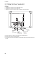
2. WIRING 2.2 Wiring the Power Supply Unit Cabling 1. Unfasten four screws to remove the cable clamp. 2. Unfasten four screws to remove the cover. 3. Attach the connectors of three cables as shown in the figure below. POWER Board 03P9419 J11 V H 2 J4 J13 V H 4 V H 5 J3 J1 3P V H 9 VL3P-VV-S2X 2C-AA050 cable (to 12-24 VDC) J5 N H 13 J12 V H 1 0 J14 N H 1 4 Ground terminal MJ-B24 LPF0011-050 cable (to display unit) Antenna cable RW-9771 (03S9771) 4.
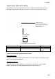
. WIRING Jumper block, slide switch setting The jumper block JP1 and slide switch S112 on the PWR board (03P9419) must be set according to radar model. Open the unit, locate JP1 and S112 and set them as below. Jumper block JP1 ("short" for FR-8252 radar; remove dummy connector and attach connector assy. XH2P-L40-ACR.
2. WIRING 2.3 Port for External Devices External equipments can be connected here as shown below. NMEA1(7P) NMEA2(7P) NMEA sentence device NMEA sentence device HDG (6P) Heading sensor PC/EXT-BUZZER (7P) External buzzer, PC, etc. This equipment can receive the following NMEA 0183 format sentences from other equipment. You will need the optional NMEA cable to connect with external equipment.
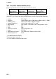
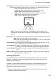
3. SETTING UP THE EQUIPMENT 3.1 Setting Language At the first power application after installation, choose a language as follows. 1. Press /BRILL key to turn the power on. “Now Initializing…” appears and after a while the window below appears. Language Language Language Language Language Language Language Language Language Language Language Language English Francais Espanol Deutsch Italiano Portugues Dansk Svensk Norsk Chinese Japanese Thai 2.
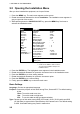
3. SETTING UP THE EQUIPMENT 3.2 Opening the Installation Menu After you have installed the equipment, set it up as follows. 1. Press the MENU key. The main menu appears on the screen. 2. Rotate the trackball downward to choose Installation. The installation menu appears in gray to right side of the screen. 3. While pressing down the CANCEL/HL OFF key, press the MENU key five times to activate the Installation menu.
3. SETTING UP THE EQUIPMENT View Position: Choose the operating position for this radar among Left, Left-Center, Center, Right-Center and Right to view echo colors correctly. The default setting is Center. Left: When operating this radar at the left side. Left-Center: When operating this radar at the left-center side. Center: When operating this radar at center position. Right-Center: When operating this radar at the right-center side. Right: When operating this radar at the right side. Approx.
3. SETTING UP THE EQUIPMENT 2. Transmit the radar at 0.25 nm range and measure the bearing of that target relative to ship’s heading with an EBL. 3. Open the Installation menu, and choose Heading Adjust. 4. Press the ENTER key to show the HEADING ADJUST window. S 0° S (0 ° ∼ 359 °) 5. Rotate the trackball upward or downward to set the value measured at the step 2 above. Confirm that the target shows dead ahead on the screen. 6. Press the ENTER key to conclude the setting.
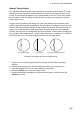
3. SETTING UP THE EQUIPMENT Manual Timing Adjust This adjustment ensures proper radar performance, especially on short ranges. The radar measures the time required for a transmitted echo to travel to the target and return to the source. The received echo appears on the display based on this time. Thus, at the instant the transmitter is fired, the sweep should start from the center of the display (sometimes called sweep origin.
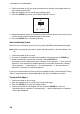
3. SETTING UP THE EQUIPMENT Manual MBS Adjust Main bang (black hole), which appears at the display center on short ranges, can be suppressed as follows. 1. 2. 3. 4. 5. Transmit the radar on the short range. Open the Installation menu and choose Manual MBS Adjust. Press the ENTER key to show the setting window. Rotate the trackball to suppress main bang (between 0 and 255). Press the ENTER key to finish. Video Initial Adjust After completing Auto Installation Setup, you can fine tune the video signal. 1.
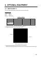
4. OPTIONAL EQUIPMENT 4.1 ARP Kit ARP-11 The ARP kit provides automatic radar plotter functions to this radar. Necessary parts Name: ARP kit Type: ARP-11 Code no.: 008-523-050 Contents of ARP kit Name ARP Board Pan head screw Spacer* Spring washer* Type 18P9014B M3x6 C2700W SQ-9 SQ-15 M3 C5191W Code No. 001-068-900 000-163-189-10 000-159-320-10 000-159-299-10 000-168-187-10 Qty 1 4 1 3 3 *Not used 1. Unscrew all connector nuts at the rear of the display unit. 2.
4. OPTIONAL EQUIPMENT 4. Mount the ARP board, mating with connectors and fixing it with four screws at the location as shown in the figure below. ARP board 5. Remount 03P9415 and 03P9413 at original position and display cover. Note: After connecting the harness to J601 on 03P9413, bend the harness so that it does not touch the parts on ARP board. 03P9413 J601 ARP board Shall not touch.
4. OPTIONAL EQUIPMENT 4.2 External Monitor You can display the radar image on an external monitor which accepts industrial standard VGA input using the optional RGB kit OP03-195. Supply monitor and interconnection cable (with HD-15P connectors of male, three rows of 15 pins) locally. Necessary parts for external monitor Name: RGB kit Type: OP03-195 Code No.: 008-553-110 Name Type Code No. RGB board 03P9492 008-553-680 Flat cable SML2SC34-4X50BDP.
4. OPTIONAL EQUIPMENT 6. Detach LCD panel from the above assembly. Be sure to disconnect the connector and flat cables. 7. Connect the cable assy. 15SDS/XHP10-005 to the rear side of the RGB board. 8. Fix the shield wire of the cable assy. with a screw used to fix the RGB board. 9. Attach the EMI core RFC-1 to the cable assy. closely to the connector. 10. Pass the signal cable through the hole shown below and then pass it through the “OPTION” port at the rear of the display unit..
4. OPTIONAL EQUIPMENT 4.3 Remote Display The FURUNO Display Unit FMD-811, MODEL1832 or GD-280/380, etc. can be connected to this radar as a sub display. The display unit RDP-150 also can be used as a sub display. To interconnect them, use optional cable MJ-B24LPF0008-100/200/300 (see page iv). Also, the EMI core (option) should be attached to the remote display cable to prevent noise. Installation materials for remote display (Type: CP03-31001、Code number: 008-556-830) Name Type Code no.
4. OPTIONAL EQUIPMENT 7. Fix the signal cable to the spacer of the FIL board with a cable tie CV-150N. Fix the cable to the spacer of FIL board with cable-tie. 8. Reassemble the display unit.
4. OPTIONAL EQUIPMENT 4.4 External Buzzer The optional external buzzer provides a louder alert when an alarm is violated. External buzzer Type: OP03-136 Code no.: 000-086-443 Further, you need the optional cable assy. MJ-A7SPF0007-050C (w/7P connector, 5 m, code no. 000-154-028-10). 1. Attach the MJ-A7SPF0007-050C cable assy. (option) to the PC/EXT-BUZZER port at the rear of the display unit. 2. Cut off the XH connector and cable itself (as necessary) at the end of the external buzzer cable. 3.
4. OPTIONAL EQUIPMENT This page is intentionally left blank.
0#/' &1%7/'06 , % /, # 52( <% %2 %2 %2 52 4&2 , ' &'5%4+26+10 %1&' ͳ 4&2 , ' 㩿㪁㪈㪀 3 6; 䯴⇛࿑䬽ኸᴺ䬾䫺ෳ⠨୯䬶䬨䫻䎃䎧䎬䎰䎨䎱䎶䎬䎲䎱䎶䎃䎬䎱䎃䎧䎵䎤䎺䎬䎱䎪䎃䎩䎲䎵䎃䎵䎨䎩䎨䎵䎨䎱䎦䎨䎃䎲䎱䎯䎼䎑䯵 㩿㪁㪈㪀䈱ᦠ㘃䈲䇮ᢥ᭽ኾ↪ 㩿㪁㪈㪀㩷㪤㪘㪩㪢㪜㪛㩷㪛㪦㪚㪬㪤㪜㪥㪫㪪㩷㪘㪩㪜㩷㪝㪦㪩㩷㪡㪘㪧㪘㪥㪜㪪㪜㩷㪪㪜㪫㩷㪦㪥㪣㪰㪅 䍘㪄䍢䍼⇟ภᧃየ䈱㪲㪁㪁㪴䈲䇮ㆬᛯຠ䈱ઍ䍘䍎䍢䍼䉕䈚䉁䈜䇯 㪚㪦㪛㪜㩷㪥㪬㪤㪙㪜㪩㩷㪜㪥㪛㪠㪥㪞㩷㪮㪠㪫㪟㩷㩹㪁㪁㩹㩷㪠㪥㪛㪠㪚㪘㪫㪜㪪㩷㪫㪟㪜㩷㪚㪦㪛㪜㩷㪥㪬㪤㪙㪜㪩㩷㪦㪝㩷
࡙࠾࠶࠻ 1 7 6 . + 0 ' +056#..#6+10 /#6'4+#.5 70+6 %2 45$ &'5%4+26+10 %1&' ͳ )6 : 㧔⇛࿑ߩኸᴺߪޔෳ⠨୯ߢߔ& ޕ+/'05+105 +0 &4#9+0) (14 4'('4'0%' 10.; 㧕 䍘㪄䍢䍼⇟ภᧃየ䈱㪲㪁㪁㪴䈲䇮ㆬᛯຠ䈱ઍ䍘䍎䍢䍼䉕䈚䉁䈜䇯 㪚㪦㪛㪜㩷㪥㪬㪤㪙㪜㪩㩷㪜㪥㪛㪠㪥㪞㩷㪮㪠㪫㪟㩷㩹㪁㪁㩹㩷㪠㪥㪛㪠㪚㪘㪫㪜㪪㩷㪫㪟㪜㩷㪚㪦㪛㪜㩷㪥㪬㪤㪙㪜㪩㩷㪦㪝㩷㪩㪜㪧㪩㪜㪪㪜㪥㪫㪘㪫㪠㪭㪜㩷㪤㪘㪫㪜㪩㪠㪘㪣㪅 #06'00# +056#..#6+10 /#6'4+#.
ᢙ㊂ 3 6; ↪ㅜ㧛⠨ 4'/#4-5 %#$.' #55; 㩃㨺㩖㩨㩣⚵ຠ '/+ %14' '/+㩄㨻 '/+ %14' '/+㩄㨻 *':#)10#. *'#& $1.6 ⷺ㩘㩨㩣㩎 *':#)10#. 076 ⷺ㩏㨹㩎 㩆㨷 (.#6 9#5*'4 㩚㩀㩨㩁ᐔᐳ㊄ 524+0) 9#5*'4 㩔㩨㩒ᐳ㊄ ฬޓޓ⒓ 0#/' ⇛ޓޓ࿑ 176.
6*4'#&'& 41& ኸಾ㩘㩨㩣㩎 9+0) 076 ಄㑆ㅧⲔ㩏㨹㩎 (.#6 9#5*'4 㩚㩀㩨㩁ਣᐔᐳ㊄ 524+0) 9#5*'4 㩔㩨㩒ᐳ㊄ 5'.( 6#22+0) 5%4'9 㩎㩡㩇㩊㨹㩕㩩㩧㩒㩆㩨 ޓ㩆㨷 47$$'4 %75*+10 㒐ᝄ㩄㩨㩛 47$$'4 %75*+10 㒐ᝄ㩄㩨㩛 ⇛ޓޓ࿑ 176.
⇟ ภ 01 %#$.' #55; 㩃㨺㩖㩨㩣⚵ຠ/, %#$.' #55; 㩃㨺㩖㩨㩣⚵ຠ/, %#$.' #55; 㩃㨺㩖㩨㩣⚵ຠ/, %#$.' #55; 㩃㨺㩖㩨㩣⚵ຠ/, ⇛ޓޓ࿑ 176.+0' ᢙ㊂ 3 6; )6 : ㆬᛯޓޓޓޓޓޓޓޓ 61 $' 5'.'%6 ㆬᛯޓޓޓޓޓޓޓޓ 61 $' 5'.'%6 ㆬᛯޓޓޓޓޓޓޓޓ 61 $' 5'.'%6 ㆬᛯޓޓޓޓޓޓޓޓ 61 $' 5'.'%6 ↪ㅜ㧛⠨ 4'/#4-5 㧲㨁㧾㨁㧺㧻ޓ㧱㧸㧱㧯㨀㧾㧵㧯ޓ㧯㧻ޓ㧚㧘㧸㨀㧰 %1&' 01 /, $ .2( %1&' 01 /, $ .2( %1&' 01 /, $ .2( %1&' 01 /, $ .
&1%7/'06 +056#..#6+10 /#6'4+#.5 52#4' 2#465 70+6 1 7 6 . + 0 ' % % %2 /, $ .2( 4 8.
(75' 㩕㨷㨺㩇㩨 (75' 㩕㨷㨺㩇㩨 ()$1 # #% 8 ()$ 8 # 2$( ()$1 # #% 8 ()$ 8 # 2$( 2'4 8'5 (75' 㩀㩧㨼㩢㩕㨷㨺㩇㩨 (75' 㩕㨷㨺㩇㩨 (75' 㩕㨷㨺㩇㩨 ()$1 # #% 8 ()$1 8 # 2$( ()$1 # #% 8 ()$ 8 # 2$( ()$1 # #% 8 ()$ 8 # 2$( &9) 01 14 6;2' 01 2'4 8'5 5'65 2'4 8'55'.
,WN 4 'UWOK D-1
Y.
Y.
Y.
Y.
C B A MJ-A3SPF0018-050ZC,5m,φ10 造船所手配。 オプション。 コネクタは工場にて取付済み。 シールドは両端で完全にアースする。 EMIコアを取り付ける。 *3 MJ-A7SPF WHT BLU YEL GRN RED BLK *3 MJ-A6SPF シロ WHT クロ BLK キ YEL ミドリ GRN *2 MJ-A7SPF0007-050C シロ 5m,φ7 アオ キ ミドリ 外部ブザー 1m アカ RED アカ EXT. BUZZER クロ BLK クロ OP03-136 *2 *2 MJ-A6SPF0003-050C/100C 5/10m,φ6 *2 MJ-A6SPF0007-100C 10m,φ6 リモートコントローラ REMOTE CONTROLLER RCU-019 *2 ヘディングセンサー HEADING SENSOR PG-1000 *2 A-Dコンバータ A-D CONVERTER AD-100 *2 NOTES *1: SHIPYARD SUPPLY. *2: OPTION. *3: FITTED AT FACTORY.
C B A 2 注記 *1) *2) *3) *4) *5) NOTE 造船所手配。 *1: SHIPYARD SUPPLY. オプション。 *2: OPTION. コネクタは工場にて取付済み。 *3: FITTED AT FACTORY. シールドは両端で完全にアースする。 *4: GROUND SHIELD EFFECTIVELY AT BOTH ENDS. EMIコアを取り付ける。 *5: ATTACH EMI CORES. *1 IV-2sq. VL3P-VV-S2X2C-AA050,5m,φ10 (03S9801) *3 10A:24V MJ-A3SPF POWER 15A:12V 指示部 MJ-A3SPF0018-050ZC 1 (+) シロ WHT 12-24 VDC DISPLAY UNIT 5m,φ10 2 (-) クロ BLK RDP-150 *1 3 GND 100/110/115/ DPYC-1.