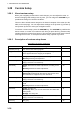
. DESCRIPTION OF OPERATION 1.28 Custom Setup 1.28.1 About custom setup When your navigating environment or task changes, you must adjust the radar. Instead of changing radar settings case by case, you can assign the CUSTOM key to provide best settings for common conditions. There are three default custom setups for the internal computer of the radar (see the table on the next page). You can adjust these settings on the [Custom 1], [Custom 2] and [Custom 3] menus to meet your navigation needs.
1. DESCRIPTION OF OPERATION Menu item Available settings See section [Pulse Length] [Short] or [Long], you can select on 1.5, 1.6, 3.0 and 3.2 nm ranges. 1.18 [Echo Stretch] [Off], [1], [2], [3] 1.22 [Echo Average] [Off], [1], [2], [Auto] 1.23 [Noise Rejector] [Off], [On] 1.30 [Wiper] [Off], [1], [2] 1.31 [Int Rejector] [Off], [1], [2], [3] 1.14 [Display-Dynamic] [Narrow]: Erase weak echoes. [Normal]: Normal use [Wide]: Display weaker echoes compared to [Narrow]. 1.
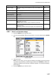
1. DESCRIPTION OF OPERATION 1.29 How to Program Function Keys (F1, F2 and F3 keys) You can program function keys (F1, F2 and F3) to provide one-touch access to a required function. Function key operation To activate a function, press function key, F1, F2 or F3. Press same key to change the setting. The default programs are [Gain Mode] for F1, [Sea Mode] for F2, [A/C Auto] for F3. When you press the F1 or F2 key, the window for Gain/Sea/Rain indicator shows. See section 1.9 and 1.10 for operation.
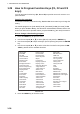
1. DESCRIPTION OF OPERATION 1.30 Noise Rejector White noise can appear on the screen as random "marks". You can reduce this noise as follows: 1. Press the MENU key to open the menu. 2. Use the Cursorpad (S or T) to select [Echo] and press the ENTER key. 3. Use the Cursorpad (S or T) to select [Noise Rejector] and press the ENTER key. Noise Rejector options 4. Use the Cursorpad (S or T) to select [Off] or [On] then press the ENTER key. 5. Press the MENU key to close the menu. 1.
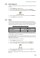
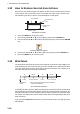
1. DESCRIPTION OF OPERATION 1.32 How to Reduce Second-trace Echoes Echoes from very distant targets can appear as false echoes (second-trace echoes) on the screen. The second-trace echo occurs when the return echo is received one transmission cycle later, or after a next transmission of radar pulse. TX repetition Second-trace echo False echo range Actual range Second-trace echoes 1. Press the MENU key to open the menu. 2. Use the Cursorpad (S or T) to select [Echo] and press the ENTER key. 3.
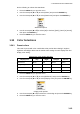
1. DESCRIPTION OF OPERATION Do the following to activate the Watchman: 1. Press the MENU key to open the menu. 2. Use the Cursorpad (S or T) to select [Alarm] and press the ENTER key. 3. Use the Cursorpad (S or T) to select [Watchman] and press the ENTER key. Watchman options 4. Use the Cursorpad (S or T) to select [Off] or the time ([5min], [10min] or [20min]) then press the ENTER key. 5. Press the MENU key to close the menu. 1.34 Color Selections 1.34.
1. DESCRIPTION OF OPERATION 1.34.2 Custom colors The custom color design lets you select preferred echo, background, characters, range rings and marks colors. Select [Custom] in the [Display Color] menu item (see section 1.34.1) to use the user selected echo, background, characters, range rings and marks colors. 1. Press the MENU key to open the menu. 2. Use the Cursorpad (S or T) to select [Brill/Color] and press the ENTER key. 3. Use the Cursorpad (S or T) to select [Echo Color] and press the ENTER key.
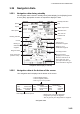
1. DESCRIPTION OF OPERATION 1.35 Navigation Data 1.35.1 Navigation data during standby The navigation data is shown in standby when [STBY Display] on the [Display] menu is set to [Nav]. Appropriate sensors are required to display the data.
1. DESCRIPTION OF OPERATION To show or hide the navigation data at the bottom of the screen, do the following: 1. Press the MENU key to open the menu. 2. Use the Cursorpad (S or T) to select [Display] and press the ENTER key. 3. Use the Cursorpad (S or T) to select [Data Box] and press the ENTER key. Data Box options 4. Use the Cursorpad (S or T) to select an option and press the ENTER key. [Off]: Turn off the data display. [Nav]: Navigation data [Target]: ARPA and AIS target data (See section 3.8 and 4.
1. DESCRIPTION OF OPERATION 1.37 Characteristics Curve You can change the characteristics curve to reduce unwanted weak echoes (sea reflections, etc.). Select [1], [2] or [3] depending on conditions when unwanted weak echoes hide wanted targets. 1. Press the MENU key to open the menu. 2. Use the Cursorpad (S or T) to select [Echo] and press the ENTER key. 3. Use the Cursorpad (S or T) to select [Display-Curve] and press the ENTER key. Display-Curve options 4.
1. DESCRIPTION OF OPERATION 1.38 Waypoint Marker The waypoint marker shows the location of the destination waypoint set on a navigation plotter. The heading signal or course data are required. You can turn on/off the waypoint marker as follows: Waypoint marker + Waypoint marker 1. Press the MENU key to open the menu. 2. Use the Cursorpad (S or T) to select [Others] and press the ENTER key. 3. Use the Cursorpad (S or T) to select [WPT Mark] and press the ENTER key. WPT Mark options 4.
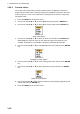
1. DESCRIPTION OF OPERATION 3. Use the Cursorpad (S or T) to select [Alarm Status] and press the ENTER key. TRIGGER HEADING BEARING GYRO VIDEO POSITION NMEA_HDG IN OUT IN OUT COLLISION LOST PROXIMITY COLLISION PROXIMITY TX ANT CH1 CH2 CH70 FAIL MKD EPFS L/L SOG COG HDG ROT OVER_TEMP Alarm Status display 4. Press the CANCEL/HL OFF key to close the alarm status display. 5. Press the MENU key to close the menu.
1. DESCRIPTION OF OPERATION Alarm category Meaning AIS SYSTEM* TX TX stopped or TX error ANT Antenna VSWR problem CH1 TDM2 RX1 board problem CH2 TDM2 RX2 board problem CH70 RX channel 70 problem FAIL System failure MKD Minimum input device lost EPFS Navigator (GPS, etc.) problem L/L Position data lost SOG Speed data lost COG Course data lost HDG Heading data lost ROT Rate of turn data lost OTHER* OVER_TEMP The temperature of the equipment is more than the specified value.
1. DESCRIPTION OF OPERATION 3. Use the Cursorpad (S or T) to select [Echo Area] and press the ENTER key. Echo Area options 4. Use the Cursorpad (S or T) to select [Normal] or [Full Screen] then press the ENTER key. 5. Press the MENU key to close the menu. 1.41 Initial Sub Menu The [Initial] sub menu in the [System] menu contains the items which allow you to customize your radar to meet your needs. 1.41.1 How to open the Initial sub menu 1. Press the MENU key to open the menu. 2.
1. DESCRIPTION OF OPERATION [Range Preset]: You can select the radar ranges. Select a range and press the ENTER key to switch on and off. At least two ranges must be turned on. 0.0625 is not available in KM (kilometers). NM (nautical miles) KM (kilometers) SM (statute miles) Available ranges [Wind Direction]: Wind direction is shown as [Apparent] or [True]. [NMEA Port 1]: Set the baud rate of the equipment connected to Port 1 ([Auto], [4800], or [38400] (bps)).
1. DESCRIPTION OF OPERATION 1.42 Units Sub Menu You can select the unit of measurement for range, ship speed, depth, temperature and wind speed on the [Units] sub menu in the [System] menu. You can not open this sub menu in normal operation. To open this menu, select [Units], hold the CANCEL/HL OFF key and press the MENU key five times.
1. DESCRIPTION OF OPERATION 5. Use the Cursorpad (S or T) to select [Sect-Blank 1 (or 2) Start] and press the ENTER key. Sect-Blank Start setting window 6. Use the Cursorpad (S or T) to set the start point of the sector and press the ENTER key. 7. Use the Cursorpad (S or T) to select [Sect-Blank 1 (or 2) End] and press the ENTER key. Sect-Blank End setting window 8. Use the Cursorpad (S or T) to set the end point of the sector and press the ENTER key.
1. DESCRIPTION OF OPERATION 1.44 Other Menu Items This section describes the menu items not previously described. 1.44.1 Menu items on the [Brill/Color] menu [View Position]: You can select the angle from where you see the screen. View Position options [Menu Transparency]: You can select the degree of transparency of the menu window so the menu window does not hide the echo display. [4] is the greatest degree of transparency. [Off] functions to hide the echo display behind the menu window completely.
1. DESCRIPTION OF OPERATION [Custom Echo Color]: You can customize the echo color with the following two methods. This function is not available in the [IEC] or [Russian-River] mode. Custom Echo Color setting window Method 1: 1) Select the echo rank to change on the [Rank] (setting range: 1 - 31). 2) Set the RGB values for selected echo rank on the [Red], [Green] and [Blue] (setting range: 0 - 63). Method 2: 1) Select 31 on the [Rank].
1. DESCRIPTION OF OPERATION 1.44.2 Menu items on the [Display] menu [Base Text Display]: You can select on/off for the text indications of the following items on the display. The settings on this function are used when you set [Echo Area] to [Full Screen] on the [Display] menu. This function is not available in the [IEC] or [Russian-River] mode. Press the ENTER key to change between on and off. Base Text Display options The text indications set to off appear when you operate any key.
1. DESCRIPTION OF OPERATION 1.44.3 Menu items on the [Echo] menu [Color Erase]: Erase the lower echo color whose level is set here. Set a large value to display only the stronger echoes. Color Erase setting window 1.45 Remote Display You can use this radar as a remote display when you set [Input Source] to [Slave] on the [Installation] sub menu. When this setting is done, the menu and display change as described below. To display the radar image on the remote display, transmit from the main radar.
1. DESCRIPTION OF OPERATION Items unavailable with Function key F1, F2 and F3 • [Pulse Length] ([Echo] menu) • [2nd Echo Rejector] ([Echo] menu) • [Watchman] ([Alarm] menu) • [Tuning Mode] ([Tuning] menu) Total TX time indication The total TX time (TX TIME XXXXXX.XH) does not appear on the diagnostic test or on the Normal standby display.
1. DESCRIPTION OF OPERATION This page is intentionally left blank.
2. DESCRIPTION OF RADAR 2.1 General 2.1.1 Minimum and maximum ranges Minimum range The minimum range is defined by the shortest distance at which, using a scale of 0.0625 or 0.125 nm, a target having an echoing area of 10 m2 is shown separate from the point representing the antenna position. The minimum range depends on the pulselength, antenna height, and signal processing (like main bang suppression and digital quantization).
2. DESCRIPTION OF RADAR 2.1.2 Radar resolution The bearing resolution and range resolution are important in radar resolution. Bearing resolution The bearing resolution is the ability of the radar to display the echoes received from two targets at the same range as the separate echoes. The bearing resolution is proportional to the antenna length and the wavelength.
2. DESCRIPTION OF RADAR 2.1.3 Bearing accuracy One of the most important features of the radar is how accurately the bearing of a target can be measured. The accuracy of bearing measurement depends on the narrowness of the radar beam. The bearing is taken relative to the heading of the ship. Correct adjustment of the heading line at installation is important to get accurate bearings.
2. DESCRIPTION OF RADAR 2.2.2 Sidelobe echoes When the radar pulse is transmitted, some radiation escapes on each side of the beam, called "sidelobes”. If a target is where a target can be detected by the sidelobes as well as the mainlobe, the side echoes can be shown on both sides of the true echo at the same range. Sidelobes show normally only on short ranges and from strong targets. You can reduce the sidelobes with the A/C SEA control.
2. DESCRIPTION OF RADAR 2.2.4 Shadow sector Funnels, stacks, masts, or derricks near the antenna interrupt the radar beam, and a non-detecting sector can occur. Targets can not be detected within this sector. Wharf and its echo Radar position Wharf and its echo Radar position Shadow sector occurs because wharf is hidden behind ship. Large ship Shadow sector occurs because obstruction (like mast) is in path of radar beam. Size of blind sector depends on size of obstruction and range.
2. DESCRIPTION OF RADAR 2.3 SART (Search and Rescue Transponder) 2.3.1 SART description When any X-band radar reaches within a range of approximately 8 nm, a Search and Rescue Transponder (SART) sends a response to the radar signal. The transmitter signal of response is 12-sweeps signal between 9,500 MHz to 9,200 MHz. The time of slow sweep signal is 7.5 μs and the time of fast sweep signal is 0.4 μs. When the radar receives this SART signal, a line of 12 dots appears.
2. DESCRIPTION OF RADAR 2.3.2 General remarks on receiving SART SART range errors When the SART is at a range greater than approximately 1 nm, the first dot is displayed at 0.64 nm beyond the true position of the SART. When the range closes so that the fast sweep responses are seen also, the first range echoes are displayed at 150 m beyond the true position. Range scale When you find the SART position, do as follows: 1. Use the RANGE key to set the range scale to 6 nm or 12 nm. 2. Turn off [A/C Auto]. 3.
2. DESCRIPTION OF RADAR 2.4 RACON A RACON is a radar beacon which emits radar-receivable signals in the radar frequency spectrum (X- or S-band). There are several signal formats; in general, the RACON signal appears on the radar screen as a rectangular echo originating at a point just beyond the position of the radar beacon. It has a Morse coded pattern. Note that the position on the radar display is not accurate.
3. ARPA OPERATION The Automatic Radar Plotter ARP-11 (option) manually or automatically acquires and tracks ten targets. Once a target is acquired automatically or manually, a target is automatically tracked within 0.1 to 16 nm. 3.1 Precautions for Use CAUTION Do not depend on one navigation device for the navigation of the ship. The navigator must check all aids available to confirm position. Electronic aids are not a replacement for basic navigation principles and common sense.
3. ARPA OPERATION 3.3 ARPA Display On/Off You can turn the ARPA display on or off. The system continuously tracks ARPA targets regardless of this setting. 1. Press the MENU key to open the menu. 2. Use the Cursorpad (S or T) to select [ARPA] and press the ENTER key. 3. Use the Cursorpad (S or T) to select [Display] and press the ENTER key. ARPA-Display options 4. Use the Cursorpad (S or T) to select [Off] or [On] then press the ENTER key. 5. Press the MENU key to close the menu. 3.
3. ARPA OPERATION 3.4.2 Automatic acquisition When you set an automatic acquisition area, the ARPA can acquire up to five targets automatically. The automatic acquisition area is 2.0 to 2.5 nm in range and ±45° on either side of the heading line in bearing. When you change the automatic acquisition to manual acquisition, targets being tracked in automatic acquisition are continuously tracked. Automatic acquisition area 45° port 2.0 - 2.5 nm 45° starboard Heading line Automatic acquisition area 1.
3. ARPA OPERATION 3. Use the Cursorpad (S or T) to select [All Cancel] and press the ENTER key. All Cancel options 4. Use the Cursorpad (S) to select [Yes] and press the ENTER key. All symbols are erased from the screen and the long beep sounds. 5. Press the MENU key to close the menu. 3.6 Vector Attributes 3.6.1 What is a vector? A vector is a line extending from a tracked target. A vector shows speed and course of the target.
3. ARPA OPERATION 3. Use the Cursorpad (S or T) to select [Vector Time] and press the ENTER key. Vector Time setting window 4. Use the Cursorpad (S or T) to select time and press the ENTER key. 5. Use the Cursorpad (S or T) to select [Vector Reference] and press the ENTER key. Vector Reference options 6. Use the Cursorpad (S or T) to select [Relative] or [True] then press the ENTER key. This function is not activate for [IEC] or [Russian-River] purpose. The mode is set to [True].
3. ARPA OPERATION 01 Vector of your ship + Cursor 04 02 03 Data box 3.7 History Display (target past position) This radar can display time-spaced dots (maximum ten dots) that mark the past positions of any tracked ARPA target. You can evaluate actions of a target by the spacing between dots. Below are examples of dot spacing and target movement.
3. ARPA OPERATION 6. Use the Cursorpad (S or T) to select [History Interval] and press the ENTER key. History Interval options 7. Use the Cursorpad (S or T) to select the time interval and press the ENTER key. 8. Press the MENU key to close the menu. 3.8 ARPA Target Data You can show the data for a tracked ARPA target in the data box at the bottom of the screen.
3. ARPA OPERATION 3.9 CPA/TCPA Alarm Set CPA (Closest Point of Approach) alarm range and TCPA (predicted Time to CPA) alarm time to alert you to targets that can be on a collision course. When CPA and TCPA of any ARPA target become less than the preset CPA and TCPA alarm settings, the audio alarm sounds. The alarm message "COLLISION" appears. The target symbol changes to a dangerous target symbol (triangle) and flashes with its vector. You can stop the audio alarm with any key.
3. ARPA OPERATION 5. Use the Cursorpad (S or T) to select [TCPA] and press the ENTER key. TCPA options 6. Use the Cursorpad (S or T) to select TCPA and press the ENTER key. 7. Press the MENU key to close the menu. 3.10 Proximity Alarm The proximity alarm alerts you when an ARPA target is within the range you set. The audio alarm sounds and the alarm message "PROXIMITY" appears. The target symbol changes to a dangerous target symbol (triangle, see section 3.9) and flashes with its vector.
3. ARPA OPERATION 3.11 Lost Target When the system detects a lost target, the audio alarm sounds and the alarm message "LOST" appears. The target symbol becomes a flashing square like the following illustration. When the system detects the target again, the target symbol becomes a normal symbol. Lost target symbol To erase a lost target symbol, put the cursor on the symbol and press the CANCEL/ HL OFF key. If you leave a lost target symbol flashing, the symbol disappears after one minute.
4. AIS OPERATION Connected to the FURUNO AIS Transponders FA-150, FA-100, FA-50 or the AIS Receiver FA-30, the MODEL 1937 can show the name, position and other navigation data of the nearest 100 AIS transponder-equipped ships. This radar accepts position data fixed by WGS-84 geodetic datum. Set the datum to WGS-84 on the GPS navigator connected to this radar. If this radar is interfaced with the FURUNO GPS Navigator GP-320B, see section 5.2 for the procedure. 4.
4. AIS OPERATION 3. Use the Cursorpad (S or T) to select [Display] and press the ENTER key. AIS-Display options 4. Use the Cursorpad (S or T) to select [Off] or [On] then press the ENTER key. 5. Press the MENU key to close the menu. 4.3 AIS Symbols When the AIS is turned on, AIS targets are displayed with AIS symbol as below.
4. AIS OPERATION When there are many activated targets on the screen, you can not easily distinguish the activated targets from the radar images or ARPA targets. You can sleep an activated target for easy view of radar images. Sleeping target To activate a target: Put the cursor on the target and press the ENTER key. To sleep a target: Put the cursor on the target and press the CANCEL HL/OFF key. 4.5 AIS Target Data You can show the AIS target data in the data box at the bottom of the screen.
4. AIS OPERATION 4.6 How to Sort Targets You can sort the AIS targets received from the AIS transponder by range from your ship, by sector, by CPA or TCPA. 1. Press the MENU key to open the menu. 2. Use the Cursorpad (S or T) to select [AIS] and press the ENTER key. 3. Use the Cursorpad (S or T) to select [Sort By] and press the ENTER key. Sort By options 4. Use the Cursorpad (S or T) to select sorting method and press the ENTER key. [Range]: Sort targets within the display range set (see section 4.
4. AIS OPERATION 4.8 How to Display the Targets within a Specific Sector You can display AIS targets only within a specific sector. If the target sorting method is selected to [Sector], the target data within the sector set here is transmitted to this radar. 1. Press the MENU key to open the menu. 2. Use the Cursorpad (S or T) to select [AIS] and press the ENTER key. 3. Use the Cursorpad (S or T) to select [Sector Start] and press the ENTER key. Sector Start setting window 4.
4. AIS OPERATION 4. Use the Cursorpad (S or T) to select the number of targets to display and press the ENTER key. 5. Press the MENU key to close the menu. 4.10 Vector Attributes 4.10.1 What is a vector? A vector is a line extending from a tracked target. A vector shows speed and course of the target. The top of a vector shows estimated position of the target after the selected vector time elapses. If you extend the vector length (time), you can evaluate the risk of collision with any target. 4.10.
4. AIS OPERATION 4.11 History Display (target past position) This radar can display time-spaced dots (maximum ten dots) that marks the past positions of any tracked AIS target. You can evaluate actions of a target by the spacing between dots. Below are examples of dot spacing and target movement.
4. AIS OPERATION 4.12 CPA/TCPA Alarm Set CPA (Closest Point of Approach) alarm range and TCPA (predicted Time to CPA) alarm time to alert you to targets that can be on a collision course. When CPA and TCPA of any AIS target (including a sleeping target) become less than the preset CPA and TCPA alarm settings, the audio alarm sounds. The alarm message "COLLISION" appears. The target symbol changes to a dangerous target symbol (red) and flashes with its vector.
4. AIS OPERATION 4.13 Proximity Alarm The proximity alarm alerts you when an AIS target is within the range you set. The audio alarm sounds and the alarm message "PROXIMITY" appears. The target symbol changes to a dangerous target symbol (red) and flashes with its vector. Press any key to stop the audio alarm and flashing. The dangerous target symbol is displayed until the target is not within the range set, the alarm range is changed to exclude the target, or the proximity alarm is deactivated. 1.
4. AIS OPERATION 4. Use the Cursorpad (S) to select [Yes] and press the ENTER key. All lost targets symbols are erased from the screen and the long beep sounds. 5. Press the MENU key to close the menu. 4.15 Symbol Color You can select the AIS symbol color among Green, Red (unavailable in the [IEC] or [Russian-River] purpose), Blue, White or Black. 1. Press the MENU key to open the menu. 2. Use the Cursorpad (S or T) to select [AIS] and press the ENTER key. 3.