
Installation Instructions

17-247-03 rev. 04 12/14/10
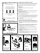
max. no speed sensor:
191mm (7-1/2")
Transom-Mount Transducer
or TRIDUCER
®
Multisensor
with Integral Release Bracket
Model P66
U. S. Patents: 5,606,253; 5,719,824
Applications
• Not recommended for boats with large inboard engine(s)
• Not recommended for stepped hull
• Good operation up to 44kn (50MPH)
• Vertically orients sound beam on hull with deadrise angle up to 30°
• Adjusts to transom angles from 2
° –22°
• Bracket protects sensor from frontal impact only
Tools & Materials
Safety goggles
Dust mask
Scissors
Masking tape
Electric drill
Drill bits:
Bracket holes 4mm, #23, or 9/64"
Transom hole (optional) 21mm or 13/16"
Cable clamp holes 3mm or 1/8"
75 mm (3")
minimum beyond
swing radius
Figure 1. Headroom required on a stepped transom
min.: 127mm (5")
Angle finder
Marine sealant (suitable for below waterline)
Screwdrivers
Straight edge
Pencil
Grommet(s) (some installations)
Cable ties
Water-based anti-fouling paint (mandatory in salt water)
Mounting Location
CAUTION: Do not mount in an area of turbulence or bubbles:
near water intake or discharge openings; behind strakes, struts,
fittings, or hull irregularities
CAUTION: Avoid mounting the sensor where the boat may be
supported during trailering, launching, hauling, or storage.
• For the best performance, the sensor must be in contact with smooth
water. To identify an area of clean water, observe the water flow off the
transom while the boat is underway.
• Allow headroom space above the bracket for it to release and rotate the
sensor upward (see Figure 1).
• Mount the sensor as close to the centerline (keel) of the boat as
possible to ensure the sensor remains in the water when the boat is
turning.
• Single drive boat—Mount at least 75mm (3") beyond the swing
radius of the propeller (see Figure 2). The starboard side where the
propeller blades are moving downward is preferred.
• Twin drive boat—Mount the sensor between the drives.
Transducer
TRIDUCER
®
multisensor
Figure 2. Mounting location on single drive boat
max. with speed sensor:
213mm (8-1/2")
headroom
INSTALLATION INSTRUCTIONSOWNER’S GUIDE &
Record the information found on the cable tag for future reference.
Part No._________________Date___________Frequency________kHz
Copyright © 2003 Airmar Technology Corp.
Copyright © 2003 Airmar Technology Corp.
NOTE: Starboard
side of hull where
propeller blades are
moving downward is
preferred.
WARNING: Always wear safety goggles and a dust
mask when installing to prevent personal injury.
WARNING: When the boat is placed in the water,
immediately check for leaks around the screws and
any other holes drilled in the hull.
CAUTION: Never pull, carry, or hold the transducer by
the cable as this may sever internal connections.
CAUTION: Never strike the multisensor with anything
except the palm of the hand. Never strike the paddlewheel.
CAUTION: Never use solvents. Cleaners, fuel, paint,
sealants, and other products may contain strong
solvents, such as acetone, which attack many plastics
greatly reducing their strength.
IMPORTANT: Please read the instructions completely
before proceeding with the installation. These
instructions supersede any other instructions in your
instrument manual if they differ.