
Installation Instructions


B175H
130 - 210 kHz
Copyright © 2008 - 2012 Airmar Technology Corp.
Follow the precautions below for optimal
product performance and to reduce the risk of
property damage, personal injury, and/or death.
WARNING: Always install the two set screws with
marine sealant applied to the threads. This will hold
the hull nut firmly in place. Failure to do so may allow
the hull nut to become loose.
WARNING: Always wear safety goggles and a dust
mask when installing.
WARNING: Immediately check for leaks when the
boat is placed in the water. Do not leave the boat
unchecked for more than three hours. Even a small
leak may allow considerable water to accumulate.
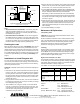
WARNING: Stainless steel housing in a metal hull—
Be sure the washer contacts the hull. Do not tighten
the hull nut with the washer against the isolation
bushing, as the housing will not be firmly installed. If
necessary, sand the isolation bushing until the washer
rests against the hull.
CAUTION: CHIRP transducer—Do not install in the
engine compartment or other hot place. The
transducer may fail if it overheats.
CAUTION: CHIRP transducer—Always operate the
transducer in water. Operating in air will allow the
transducer to overheat resulting in failure.
CAUTION: The arrow on the top of the transducer
must point toward the keel or centerline of the boat.
This will align the angle of the element inside the
transducer with the deadrise angle of your hull.
CAUTION: Never install a metal transducer on a
vessel with a positive ground system.
CAUTION: Never pull, carry, or hold the transducer by
its cable; this may sever internal connections.
CAUTION: Stainless steel housing in a metal hull—
Stainless steel housing must be isolated from a metal
hull to prevent electrolytic corrosion. Use the isolation
bushing supplied.
CAUTION: Never use solvents. Cleaners, fuel, sealants,
paint, and other products may contain solvents that can
damage plastic parts, especially the transducer’s face.
IMPORTANT: For optimal performance, apply marine
sealant to the entire inside surface of the spacer. This
will fill the gap between the spacer and the sidewall of
the transducer preventing vibration.
IMPORTANT: Read the instructions completely
before proceeding with the installation. These
instructions supersede any other instructions in your
instrument manual if they differ.
17-458-01 rev. 07 01/12/13
Thru-Hull, 1kW
Tilted Element
™
Transducer
Tilt Angles: 0°, 12°, 20°
Models: B164, B175H/M/L, SS164, SS175H/M/L
Pairs: B264N, B264W, SS264N, SS264W
U.S. Patent No. 7,369,458. UK Patent No. 2 414 077. U.S. Patent Pending
Applications
• Bronze housing recommended for fiberglass or wood hulls.
Never install a bronze housing in an aluminum hull, because
electrolytic corrosion will occur.
• Stainless steel housing compatible with all hull materials.
Recommended for metal hulls to prevent electrolytic corrosion
provided the stainless steel housing is isolated from the metal hull.
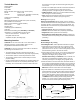
Match Tilt Angle of Transducer to Deadrise
Be sure your transducer model matches the deadrise angle of
your hull at the selected mounting location. The tilt angle is printed
on the top of the transducer (see Figure 1). To measure the
deadrise angle of your hull at the selected mounting location, use
an angle finder or a digital level (see Figure 2).
• 0° transducer for deadrise angles from 0° to 7°
• 12° transducer for deadrise angles from 8° to 15°
• 20° transducer for deadrise angles from 16° to 24°
Record the information found on the cable tag for future reference.
Part No._________________Date___________Frequency________kHz
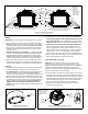
Figure 2. Deadrise angle of the hull
transom view
deadrise angle
slope of hull
parallel to waterline
INSTALLATION INSTRUCTIONSOWNER’S GUIDE &
Copyright © 2005 Airmar Technology Corp.
tilt angle
Figure 1. Top of transducer (0° model shown)