
Installation Instructions


inboard
Tools & Materials
Safety goggles
Dust mask
Angle finder
Electric drill with 10mm (3/8") or larger chuck capacity
Drill bit: 3mm or 1/8"
Hole saw: 95mm or 3-3/4" (fiberglass or wood hull)
105 mm or 4" (metal hull)
Grinder (some installations)
Sandpaper
Mild household detergent or weak solvent (such as alcohol)
File (installation in a metal hull)
Marine sealant (suitable for below waterline)
Allen wrench: 3/16"
Slip-joint pliers
Grommet(s) (some installations)
Cable ties
Water-based anti-fouling paint (mandatory in salt water)
Installation in a cored fiberglass hull (see page 4):
Hole saw for hull interior: 115mm or 4-1/2"
Fiberglass cloth and resin
or Cylinder, wax, tape, and casting epoxy
Mounting Location
CAUTION: Do not mount in line with or near water intake or
discharge openings, or behind strakes, fittings, or hull
irregularities that will disturb the water flow.
CAUTION: Do not mount in line with trailer rollers or bunks that
may damage the transducer’s face.
• The water flowing under the hull must be smooth with a
minimum of bubbles and turbulence (especially at high speeds).
• The transducer must be continuously immersed in water.
• The transducer beam must be unobstructed by the keel or
propeller shaft(s).
• Choose a location away from interference caused by power and
radiation sources such as: the propeller(s) and shaft(s), other
machinery, other echosounders, and other cables. The lower
the noise level, the higher the echosounder gain setting that
can be used.
• Choose an accessible spot inside the vessel with a minimum of
178 mm (7") of headroom for the height of the housing,
installing the spacer, and tightening the nut and set screws.
• CHIRP transducer—Mount in a cool well-ventilated area away
from the engine to avoid overheating.
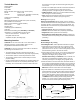
• Pairs—Mount the transducers across from one another on
opposite sides of the centerline (keel) (see Figure 3).
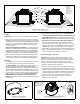
Hull Types (see Figure 4)
Planing hull powerboats—Mount well aft, near the centerline,
and well inboard of the first set of lifting strakes to ensure that the
transducer will be in contact with the water at high speeds. The
starboard side of the hull where the propeller blades are moving
downward is preferred.
• Outboard and I/O—Mount just forward of the engine(s).
• Inboard—Mount well ahead of the propeller(s) and shaft(s).
• Stepped hull—Mount just ahead of the first step.
• Boat capable of speeds above 25kn (29MPH)—Review the
installation location and operating results of similar boats before
proceeding.
Installation
Hole Drilling & Dry Fitting
Cored fiberglass hull—Follow separate instructions on page 4.
1. From inside the hull, using the hull nut as a guide to ensure
ample space, mark the center point. Then drill a 3mm or 1/8"
pilot hole. If there is a rib, strut, or other hull irregularity near the
selected mounting location, drill from the outside.
2. Using a 95mm or 3-3/4" hole saw, cut a hole from outside of the
hull perpendicular to the hull surface. It may be necessary to
enlarge the hole slightly using a grinder or file.
Stainless steel housing in a metal hull—Use a 105 mm or 4"
hole saw to accommodate the isolation bushing. It may be
necessary to enlarge the hole slightly using a grinder or file.
3. Sand and clean the area around the hole, inside and outside, to
ensure that the sealant will adhere properly to the hull. If there is
any petroleum residue inside the hull, remove it with either mild
household detergent or a weak solvent (alcohol) before sanding.
Metal hull—Remove all burrs with a file and sandpaper.
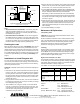
4. Dry fit the transducer to determine if the spacer must be cut.
From outside the hull, push the housing through the mounting hole
(see Figure 5). From inside, slide one of the washers onto the
housing. Slide the spacer onto the housing with the open end
facing the hull. Add the remaining washer. Be sure a minimum
of THREE threads are showing on the housing above the
washer. If not, cut the spacer to make it shorter. When cutting
the spacer, be sure to cut the open end (see Figure 6).
2
Figure 4. Best location for the transducer
stepped hull
outboard and I/O
Copyright © 2007 - 2011 Airmar Technology Corp.
Figure 3. Connecting a Pair—single transmission line
Copyright © 2008 Airmar Technology Corp.
200kHz 50kHz
pigtail