
Installation Instructions


Pairs
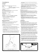
• Single transmission line fishfinder—Connect the 10m (33')
cable of the 200kHz transducer to the 1m (3') pigtail of the
50kHz transducer. Connect the remaining 10m (33') cable to
the fishfinder (see Figure 3).
• Dual transmission line fishfinder—Do not use the pigtail on
the 50kHz transducer. Fasten it to the main cable with a cable
tie. Connect the 10m (33') cable of the 50kHz transducer to the
low-frequency (50kHz) input on the fishfinder and the 200kHz
transducer cable to the high-frequency (200kHz) input.
Checking for Leaks
When the boat is placed in the water, immediately check around
the transducer for leaks. Note that very small leaks may not be
readily observed. Do not leave the boat in the water for more than
3 hours before checking it again. If there is a small leak, there may
be considerable bilge water accumulation after 24 hours. If a leak
is observed, repeat “Bedding” and “Installing” immediately (see
page 3).
Installation in a Cored Fiberglass Hull
The core (wood or foam) must be cut and sealed carefully. The
core must be protected from water seepage, and the hull must be
reinforced to prevent it from crushing under the hull nut allowing
the housing to become loose.
CAUTION: Completely seal the hull to prevent water seepage into
the core.
1. Drill a 3mm or 1/8" pilot hole from inside the hull (see Figure 8).
If there is a rib, strut, or other hull irregularity near the selected
mounting location, drill from the outside. (If the hole is drilled in
the wrong location, drill a second hole in a better location. Apply
masking tape to the outside of the hull over the incorrect hole
and fill it with epoxy.)
2. Using the 95mm or 3-3/4" hole saw, cut a hole from outside the
hull through the outer skin only. It may be necessary to enlarge
the hole slightly using a grinder.
3. From inside the hull, using the 115mm or 4-1/2" hull interior
hole saw, cut through the inner skin and most of the core. The
core material can be very soft. Apply only light pressure to the
hole saw after cutting through the inner skin to avoid
accidentally cutting the outer skin.
4. Remove the plug of core material, so the inside of the outer skin
and the inner core of the hull is fully exposed. Sand and clean
the inner skin, core, and the outer skin around the hole.
5. If you are skilled with fiberglass, saturate a layer of fiberglass cloth
with a suitable resin and lay it inside the hole to seal and strengthen
the core. Add layers until the hole is the correct diameter.
Alternatively, a hollow or solid cylinder of the correct diameter
can be coated with wax and taped in place. Fill the gap between
the cylinder and hull with casting epoxy. After the epoxy has set,
remove the cylinder.
6. Sand and clean the area around the hole, inside and outside, to
ensure that the marine sealant will adhere properly to the hull. If
there is any petroleum residue inside the hull, remove it with
either mild household detergent or a weak solvent (alcohol)
before sanding.
7. Proceed with “Bedding” on page 3.
Maintenance & Replacement
Anti-fouling Paint
CAUTION: Do not paint the exposed temperature button. Paint
will slow the response time.
Surfaces exposed to salt water must be coated with anti-fouling
paint. Use water-based anti-fouling paint only. Never use ketone-
based paint, since ketones can attack many plastics possibly
damaging the transducer. Reapply anti-fouling paint every 6
months or at the beginning of each boating season.
Cleaning
Aquatic growth can accumulate rapidly on the transducer’s face,
reducing its performance within weeks. Clean the surface with a
Scotch-Brite® scour pad and mild household detergent, being
careful to avoid making scratches. If the fouling is severe, lightly
wet sand it with fine grade wet/dry paper.
Replacement Transducer & Parts
The information needed to order a replacement transducer is printed
on the cable tag. Do not remove this tag. When ordering, specify the
part number, date, and frequency in kHz. For convenient reference,
record this information on the top of page one.
Lost, broken, or worn parts should be replaced immediately.
Obtain parts from your instrument manufacturer or marine dealer.
Gemeco Tel: 803-693-0777
(USA) Fax: 803-693-0477
email: sales@gemeco.com
Airmar EMEA Tel: +33.(0)2.23.52.06.48
(Europe, Middle East, Africa) Fax: +33.(0)2.23.52.06.49
email: sales@airmar-emea.com
Model Hull Nut Spacer Isolation Bushing
B164
B175H, B175M, B175L
B264N, B264W
02-136-02 04-677-01 —
SS164
SS175H, SS175M, SS175L
SS264N
SS264W
02-136-01 04-677-01 04-676-01
AIRMAR
TECHNOLOGY CORPORATION
35 Meadowbrook Drive, Milford, New Hampshire 03055-4613, USA
• www.airmar.com
Copyright © 2007 - 2013 Airmar Technology Corporation. All rights reserved.
4
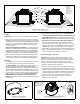
Figure 8. Preparing a cored fiberglass hull
inner skin
core
outer skinsolid or hollow cylinder
pour in
casting
epoxy
9-12 mm
(3/8-1/2")
larger than the
hole through the
hull’s outer skin
hull thickness
Copyright © 2005 Airmar Technology Corp.