2. WIRING are required (for antenna and Processor Units). See section 2.11 and the interconnection diagram for connections in the junction box. The Cable Extension Kit (Type: OP03-224-3, Code No.: 001-254-410), comprised of two junctions boxes, one LAN Signal Converters and necessary hardware, is available as an optional extra. Note: Only the RW-9600 cable can be used for foremast installation. The RW-6895/ 4873 cables are not available.
. WIRING 3. Loosen two screws on the BNC case. Attach the coaxial cable from the Antenna Unit then close the case. Fasten shield with clamp. BNC case Loosen two screws. 14 14 5 Fasten conductor with screw. Folded shield (mm) 4. Fasten the BNC case to the original position in the Antenna Unit with original two screws, referring to step 2. 5. Mount the transceiver unit to the Antenna Unit. 6. Re-connect the coaxial cable (disconnected at step 1). 2.10.
2. WIRING 3. Loosen the screws (C) on the BNC case assembly, then attach the BNC case assembly to the original position in the Processor Unit. (C) BNC case assembly 4. After attaching, adjust the position of the BNC case, then fasten the two loose screws (C) tightly. 2.10.4 How to check the installation Observe the LEDs on the converter to check for proper operation and troubleshooting.
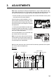
2. WIRING Fix wires with cable ties. Clamp outer conductor of coaxial cables. 15 14 13 12 11 10 9 8 7 6 5 4 3 2 1 RG12/UY RG-12/UY RW-9600/6895/4873 DPYCY-6 Connect inner conductors. 2.12 M8 screw for grounding Intelligent HUB (option) Secure the LAN cables to the cable clamps on the HUB-3000 with cable ties (supplied). Power Fail DPYC-1.5 LAN cable Power port DPYC-1.5 Ground wire (IV-1.25sq., supplied) No use. LAN port To gateway network (ECDIS, radar, etc.
2. WIRING 2.13 VDR Connection The Processor Unit has the DVI-I port or the LAN port for connection of a VDR. 2.13.1 DVI-I (Analog RGB) port connection • Use the optional RGB cable (DVI-BNCX5+GND-L2.0) to connect the VDR. • The DVI-D port and DVI-I port have their own circuits. This prevents interruption of the radar picture shown on the main monitor connected to the DVI-D port, if a fault condition occurs at the DVI-I port.
ADJUSTMENTS Note: After completing the settings and adjustments, copy the setting data to a SDcard* (USB flash memory* for C-type radars), referring to the Operator's Manual. This will allow easy restoration of setting data after the MAIN Board is replaced, etc. *: The SD card slot is in front of the Processor Unit, and the USB flash memory slot is connected to the RP board 03P9657. At the first start-up after installation, turn on the Processor Unit with the main switch.
3.
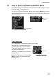
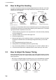
3. ADJUSTMENTS 3.1 How to Open the Radar Installation Menu The [RADAR INSTALLATION] menu has various items through two pages for adjustment of the radar. To show this menu; For RCU-014: Press and hold the HL OFF key, then press the MENU key five times. For RCU-015/016: Put the cursor on the [MENU] box. Press and hold the F1 key, then right-click five times. Page 1 Page 2 Go back to page 1. Go to page 2. Tuning initialization Tuning initialization is required before setting up the radar.
3. ADJUSTMENTS 3.2 How to Align the Heading You have mounted the Antenna Unit facing straight ahead in the direction of the bow. Therefore, a small but conspicuous target dead ahead visually must appear on the heading line (zero degrees).
3. ADJUSTMENTS • The range of target echoes is incorrect. 1. Set the GAIN, A/C SEA and A/C RAIN controls shown below. GAIN: 80 A/C SEA: Fully counterclockwise (OFF) A/C RAIN: Fully counterclockwise (OFF) 2. Open the [RADAR INSTALLATION] menu, then select [ECHO ADJUSTMENT] menu. 3. Select [TIMING ADJ VALUE] to set the value for adjustment timing manually. The setting range is 0000 to 4095.
3. ADJUSTMENTS 3.5 Other Settings This section describes the menu items not previously described. 3.5.1 [ECHO ADJUSTMENT] menu Open the main menu then select [RADAR INSTALLATION] [ECHO ADJUSTMENT] to open the [ECHO ADJUSTMENT] menu. Page 1 ECHO ADJUSTMENT(1/2) Page 2 ECHO ADJUSTMENT(1/2) 1 BACK 2 EAV MODE A/B 0 NEXT Go back to page 1. Go to page 2. [VIDEO ADJUST VALUE] Adjust the video level manually to remove noise.
3. ADJUSTMENTS [VIDEO CONTRAST] Select [ADVANCE] to clarify the echo image difference (default: [ADVANCE]). 1 LEVEL A LEVEL B LEVEL CONTRAST 3 2 CONTRAST 4 CONTRAST CONTRAST [VIDEO CONTRAST] set to [ADVANCE] at installation: C LEVEL [VIDEO CONTRAST] set to [LEGACY] at installation: CONTRAST 4 32 1 CONTRAST C B A [CLOSE TGT ES MODE] The [ECHO STRETCH] menu can enlarge the whole targets of the screen (Main menu [ECHO] [CUSTOMIZED ECHO] [ECHO STRETCH]).
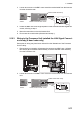
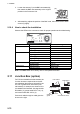
3. ADJUSTMENTS Setting (Effect level pattern) [3] [4] [5] 3.5.2 Distance 1 Distance 2 Distance 3 Medium Medium Strong weak weak Medium — weak weak [OWN SHIP INFO] menu Enter the length and width of the ship, and scanner, GPS antenna and conning positions, referring to the description and figure below. Note: This radar uses [CONNING POSITION] for CCRP and [SCANNER POSITION] for ANT as reference points for measurements and calculations.
3. ADJUSTMENTS 3.5.3 [SCANNER] menu Open the main menu then select [RADAR INSTALLATION] [SCANNER] to open the [SCANNER] menu. Note: [SCANNER] menu items differ depending on the software version, as shown in the figures to the right. [SECTOR BLANK1(2)] Set area(s) where to prevent transmission. Heading must be properly aligned (see section 3.2) before setting any blind sector. For example, set the area where For the radars For the radars an interfering object at the rear of (software version “01.
3. ADJUSTMENTS [ANT STOPPED] For qualified technician. [ANT STOPPED] prevents transmission while the antenna is stopped in STBY (default: [STBY]). [DUAL RADAR SETTINGS] When installing two FAR-2xx8 series radars, the image from both radars (main radar and external radar) may be shown together on one radar display. Image from main radar Note 1: This function is NOT available between the FAR-2xx8 radar and other radars.
2. WIRING Plastic cover Cable clamp Clamp the sheath. Power cable Power cable cover 4. Remount the plastic cover and the power cable cover. Connection of cables for serial, contact signal lines and sub monitors of ECDIS 1. Unfasten the four bolts dashed circled below to remove the upper plate of the cable clamp. 2. Remove the spacers to pass the appropriate cables on the upper and lower plates. The recommended cable entrances are shown as below.
2. WIRING 3. Fasten the cables to the post part of the plates with cable ties (local supply). Note: Be sure the vinyl sheath on the post. Cable tie Ground termimal Ground termimal Spacer Vinyl sheath Shield Vinyl sheath Cable tie Sub monitor cable Cable tie Serial cable Upper plate Lower plate 4. Pass the cables to the TB board 03P9648 and 03P9562 through the locking wire saddles (A, B and C) in the figure shown right. For the cables on the upper plate, use locking wire saddles (A and B).
2. WIRING 2. Remove the appropriate spacer to pass the cable for Control Unit on the lower plate. The recommended cable entrance is shown as below. Lower plate Control Unit 3. Fasten the cable to the post part of the plate with a cable tie (local supply). Note: Be sure the vinyl sheath on the post. Control unit cable Lower plate 4. Pass the cables to the TB board 03P9648 and clamp the shield of the cable with the cable clamp (A) shown in the following figure. Then, connect to J611 and J612.
2. WIRING For VDR connection, the RGB signal can be output with using the optional DVI-BNC cable kit OP03-252 (Code No.: 001-496-900). 1. Attach the five connectors of the Cable Assembly (supplied) to the fixing plate (supplied) with cable ties as below. 2. Establish the ground system on the fixing plate. 3. Fix the cable assembly to the appropriate location with two screw (M5). The location must be within 200 cm of the Processor Unit. 4. Connect the VDR cables to the connectors of the cable assembly. 1.
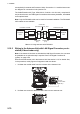
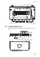
2. WIRING 2.9 Monitor Unit For the wiring of the monitor unit, see the operator’s manual supplied with the monitor unit. Mounting considerations Standard type • Connect the radar main monitor to the DVI1. • Connect the sub radar monitor to the DVI2. VDR connection To connect a VDR, it is necessary to output data in analog format. To connect a VDR to the DVI-I port, use the optional DVI-BNCX5+GND-L2.0 cable to output the RGB signal from the DVI-I. See the operator’s manual supplied with the VDR.
2. WIRING How to open the [INSTALLATION SETTING] menu Turn off the monitor unit. While you hold the DISP key, press the BRILL key to turn on the monitor unit. Keep the DISP key pressed until the [INSTALLATION SETTING] menu appears. Note: When the [DVI PWR SYNC] slide switch is ON, turn on the connected external equipment while you press the DISP key to turn on the monitor unit. 2.10 LAN Signal Converter The LAN Signal Converter allows the use of existing antenna cable RW-9600/6895/ 4873 for TR-UP radar.