
Users Manual Part 6
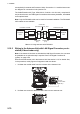
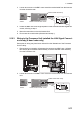
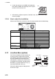
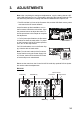
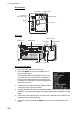
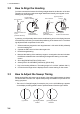

Table Of Contents

2. WIRING
2-71
3. Loosen two screws on the BNC case. Attach the coaxial cable from the Antenna
Unit then close the case.
4. Fasten the BNC case to the original position in the Antenna Unit with original two
screws, referring to step 2.
5. Mount the transceiver unit to the Antenna Unit.
6. Re-connect the coaxial cable (disconnected at step 1).
2.10.3 Wiring in the Processor Unit installed the LAN Signal Convert-
er already (X-band radar only)
Some parts or wiring may have been omitted from the illustrations of the Processor
Unit for clarity.
1. Disconnect the connection (A) between the converter and BNC case. Unfasten
two screws (B) on the BNC case assembly to remove the BNC case assembly
from the Processor Unit.
2. Loosen two screws on the BNC case. Attach the coaxial cable from the Antenna
Unit.
BNC
case
Fasten conductor with screw.
Fasten shield with clamp.
Loosen two
screws.
1414
1414
55
Folded shield
(mm)
(B)
(B)
(A)
(A)
Converter
Converter
BNC case
BNC case
BNC
case
Fasten conductor with screw.
Fasten shield with clamp.
Loosen two
screws.
1414
1414
55
Folded shield
(mm)