
Users Manual Part 6
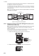
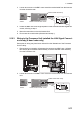
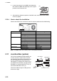
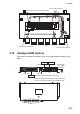
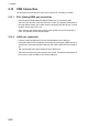
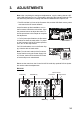
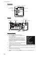
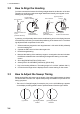

Table Of Contents

2. WIRING
2-72
3. Loosen the screws (C) on the BNC case assembly,
then attach the BNC case assembly to the original
position in the Processor Unit.
4. After attaching, adjust the position of the BNC case, then fasten the two loose
screws (C) tightly.
2.10.4 How to check the installation
Observe the LEDs on the converter to check for proper operation and troubleshooting.
Note: The TEST button is for factory use. Do not operate the button.
2.11 Junction Box (option)
For FAR-2x18/2x28/2x38 X-band radars, the
Junction boxes are required when the dis-
tance between the Antenna Unit and Proces-
sor Unit is greater than 100 meters (max.
460 meters); for example, the Antenna Unit
is installed on the foremast. Use signal cable
RW-9600 (2), power cable DPYCY-6 (3),
and coaxial cable RG-12/UY(3).
Pass each cable through its cable gland as
shown to the right.
LED State Meaning
PWR OFF Power OFF
Lighting green Power ON
Flashing orange Test mode
LAN OFF Link down
Lighting green 100 M link up
Flashing green 100 M active
Lighting orange 10 M link up
Flashing orange 10 M active
Coax/PLC OFF Link down
Lighting green Link up
Master/Slave Lighting green Master mode
Lighting orange Slave mode
(C)(C)
BNC case assembly
Master/Slave
Coax/PLC
LAN PWR
TEST
M S
HMC-200CE-A
Flat washer
Cable gland
Vinyl sheath
Clamping
gland
Gasket
Cut and trim armor.