
Users Manual Part 6
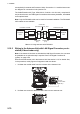
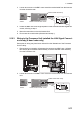

Table Of Contents
2. WIRING
2-74
2.13 VDR Connection
The Processor Unit has the DVI-I port or the LAN port for connection of a VDR.
2.13.1 DVI-I (Analog RGB) port connection
• Use the optional RGB cable (DVI-BNCX5+GND-L2.0) to connect the VDR.
• The DVI-D port and DVI-I port have their own circuits. This prevents interruption of
the radar picture shown on the main monitor connected to the DVI-D port, if a fault
condition occurs at the DVI-I port.
• The Processor Unit continuously outputs video signals from its DVI-D and DVI-I
ports. The operator cannot stop the output.
2.13.2 LAN2 port connection
• Connect a VDR complied to IEC-61162-450 standards to the LAN2 port.
• If the [VDR LAN OUTPUT] setting is set to [ON], the screenshot (JPEG-format) is
output every 15 seconds through LAN2 port. See “[VDR LAN OUTPUT]”on page 3-
24.
• The output image at the same resolution as the DVI-D port.
• The LAN2 port and DVI-D port have their own circuits. This prevents interruption of
DVI-D port, if a fault condition occurs at the LAN2 port.