
Users Manual Part 7


2. WIRING
2-63
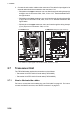
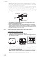
1. Remove the spacers to pass the antenna cable on the upper plate.
2. Fasten the cable to the post part of the plate with a cable tie (local supply).
Note: Be sure the vinyl sheath of the cables is on the post.
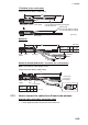
3. Pass the cable to connect the WAGO connector on the TB Board 03P9648
through the locking wire saddles as below.
For retrofit, the extra cables should be grounded on the ground terminal shown as
below. For the connection between the BNC case and the coaxial cable, see
section 2.10.3.
4. Connect the shield line of the antenna cable to the nearest ground terminal on the
plate.
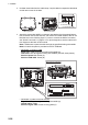
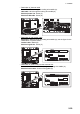
Connection of Power cable
1. Unfasten two screws to open the power cable cover.
2. Remove the plastic cover and cable clamp to pass the power cable.
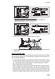
3. Connect the cable to the terminal with the pre-attached crimp-on lugs. Clamp the
power cable on the sheath.
Note: For DC power specifications, the Processor Unit does not have the main
switch. Connect each polarity (1: +, 2: –) of the cable correctly to the terminal
board.
Upper
plate
Cable tie
Cable tie
Armor
Antenna cable
Ground terminal
WAGO connection of
Antenna cable (J608)
LAN connection of
Antenna cable
Ground terminal
For RW-00135/00339 cable
WAGO connection of
Antenna cable (J608)
Ground terminal
For retrofit cable
BNC case
Coaxial cable