
Users Manual Part 7

2. WIRING
2-52
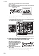
Connection of cable for Processor Unit
1. Connect the lines of the cable to the appropriate WAGO connectors (TB704), re-
ferring to the interconnection diagram at the back of this manual.
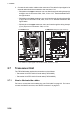
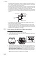
2. Set the cable for Processor Unit on
the upper cable entrance as shown
below, and fasten the armor part of
the cable with the cable clamp.
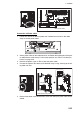
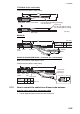
3. Connect the lines of the cable for Processor Unit as shown below through the wir-
ing clamp (B).
• Serial lines: TB704
• Shield line: Screw (A)
• LAN cable: J503
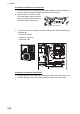
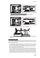
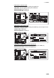
Connection of cable for Control Unit
1. Connect the lines of the cable to the appropriate WAGO connectors (TB711 and
TB712), referring to the interconnection diagram at the back of this manual.
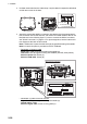
Cable for Processor Unit
Cable for Processor Unit
TB704
J503 (LAN cable)
(A)
(B)