
Users Manual Part 7

2. WIRING
2-54
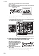
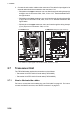
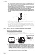
2. Connect the sub monitor cables to the connectors. The cable for input signal of an
external radar should be connected to the connector J710.
• RW-4864 on the upper entrances: max. two lines through the wiring clamps (A)
and (B) to two of connectors J708, J709, J710 or J717. See the dashed lines in
the figure below.
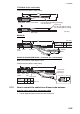
• RW-4864 on the lower entrances: max. two lines through the wiring clamps (B)
to (E) to two of connectors J708, J709, J710 or J717. See the solid lines in the
figure below.
• RW-00136 on the upper entrances: max. two lines through the wiring clamps
(C) to (E) to two of connectors J708, or J710.
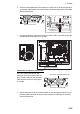
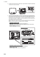
2.7 Transceiver Unit
The TR-DOWN radar requires the transceiver unit as follows:
• Transceiver Unit RTR-108 for X-band radar (FAR-2328W)
• Transceiver Unit RTR-109 for S-band radar (FAR-2338SW)
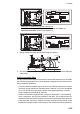
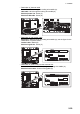
2.7.1 How to fabricate the cables
For how to connect the LAN modular plug, see "LAN cable" on page 2-5. For how to
connect the WAGO connector, see "WAGO connector" on page 2-6.
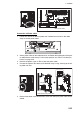
J710*
(A)(A)
(B)(B)
J710*
For RW-4864 cable For RW-00136 cable (from upper entrance)
*: For cable for “input” signal of an external radar, connect to J710.
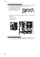
J709
J717
(C)(C)
(D)(D)
(E)(E)
(C)(C)
(D)(D)
(E)(E)
J708
J708