
Users Manual Part 7

2. WIRING
2-57
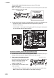
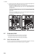
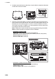
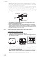
• Destination of Serial cable from the Antenna Unit
Serial cable: TB802 and TB803 through the locking wire saddle (A).
Shield of serial cable: Screw on fixing plate (C)
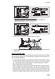
4. Bind all cables with cable ties supplied locally (two places).
5. Check that armor of cables are lying in their respective cable slots then fasten the
cable clamp.
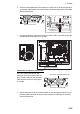
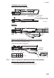
Flexible waveguide (FR-9)
The RF interconnection between the Antenna Unit and the transceiver can be made
with a flexible waveguide (FR-9). If the rectangular waveguide is used, observe the fol-
lowing installation guidelines.
• Correctly installed waveguide runs ensure the most efficient transmission of electri-
cal energy at high frequencies. Electrical losses, however, occur in the waveguide
runs. To minimize them the following factors are of great importance: minimum
length, airtightness and electrical continuity.
• Another consideration required is that of frequency disturbance. The transmitting
valve, a magnetron, is the primary oscillator in the radar. This is different from the
oscillation system at lower frequencies in which conventional radio valves are used.
In the latter case, the primary oscillator is always protected from the effects of load
impedance by a buffer stage so that frequency and waveform are left unobstructed.
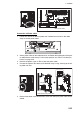
A
C
TB803
TB804
A
C
TB803
TB802
Cable tie
Cable tie