
How-To Guide


2. INITIAL SETUP
17
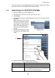
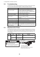
How to align the antenna heading
You have mounted the antenna unit facing straight ahead in the direction of the bow.
Therefore, a small but conspicuous target dead ahead visually should appear on the
heading line (zero degrees).
You may observe a minor bearing error on the display. This is due to the difficulty in
orienting the radar accurately. The following adjustment will compensate for the error.
[Enable Sector Blanking]/
[Enable Sector Blanking2]
Up to two sectors may be selected for blanking (no trans-
mission). Select [ON] to enable this feature. Set the start
and end angles (0° to 359°).
[Antenna Height] Select the height of the antenna above the waterline.
[Antenna Length] Selects the length of the antenna. RezBoost function re-
flects the selection of this menu item.
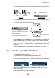
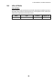
[Antenna Longitudinal Po-
sition]
Referring to the figure on the right, enter the ra-
dar antenna positioning bow-stern (Longitudi-
nal) and port-starboard (Lateral) position from
the origin.
[Antenna Lateral Position
(-Port)]
[Radar Monitoring] Display various information regarding the connected ra-
dar.
[ARPA Advanced Settings] For service technician only. Do not change these settings.
This menu item is available when setting the radar in
transmit.
[TX Channel] Select [1],[2] or [3], the channel where the interference is
smallest.
[Target Analyzer Mode] You can emphasize rain clutter or target echoes when the
target analyzer is active. Select [Rain] or [Target] as ap-
propriate.
[Auto Acquire by Doppler] When selecting [ON], approaching targets within 3 NM
from own ship are automatically acquired by the Doppler
calculated from the radar echo.
[Hardware Factory Default] Resets the radar selected at [Radar Source] to factory de-
fault.
[Reset Default Settings] Resets [Radar] menu settings to default.
Menu item Description
Origin
Origin
000
010
020
030
040
050
060
070
080
090
100
110
120
130
140
150
160
170
180
190
200
210
220
230
240
250
260
270
280
290
300
310
320
330
340
350
000
010
020
030
040
050
060
070
080
090
100
110
120
130
140
150
160
170
180
190
200
210
220
230
240
250
260
270
280
290
300
310
320
330
340
350
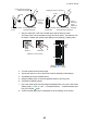
Correct bearing of target
(relative to heading)
a
Displayed
position
of target
a
Target
Antenna oriented
to port
Picture appears with
clockwise deviation.
Displayed position of target
b
Target
b
Correct
bearing of
target
(relative to
heading)
Antenna oriented
to starboard
Picture appears with
counterclockwise deviation.