Back COLOR SCANNING SONAR MODEL CSH-23/23F/24/24F
The paper used in this manual is elemental chlorine free. FURUNO Authorized Distributor/Dealer 9-52 Ashihara-cho, Nishinomiya 662-8580, JAPAN Telephone : 0798-65-2111 Fax 0798-65-4200 : All rights reserved. Printed in Japan FIRST EDITION :NOV. : NOV. 1997 J3 Pub. No. IME-13040-J3 ( TATA ) CSH-23/24/F : OCT.
SAFETY INSTRUCTIONS WARNING WARNING Do not open the cover unless totally familiar with electrical circuits and service manual. Install the specified transducer tank in accordance with the installation instructions. If a different tank is to be installed the shipyard is solely responsible for its installation, and it should be installed so the hull will not be damaged if the tank strikes an object.
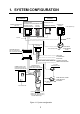
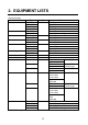
TABLE OF CONTENTS 1. SYSTEM CONFIGURATION ............................................................................ 1 2. EQUIPMENT LISTS .......................................................................................... 2 3. MOUNTING THE EQUIPMENT 3.1 Mounting the Hull Unit and Receiver Unit ........................................................................3 3.2 Mounting the Display Unit/Sub-display Unit .....................................................................9 3.
1.
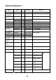
2.
Optional Equipment Name FNZ Joint Box Set-down Transformer E/S Interface Unit Sub-Display Unit Hood Hood Filter Filter Extension Cable Set (with inst. materials) 37C Cable 7C Cable 16P Cable Handle Assembly Mounting Fixture Automatic Raise Modification Kit ROM Option Kit A ROM Option Kit B Hull Unit Ant slamming Kit Type CS-170 PT-400 Mass (kg) 2 22 Code No.
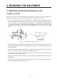
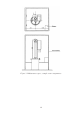
3. MOUNTING THE EQUIPMENT 3.1 Mounting the Hull Unit and Receiver Unit Location of hull unit Decide the location of the hull unit through consultation with the dockyard and shipowner. When deciding the location, the following points should be taken into account. • Select an area where propeller noise, cruising noise, air bubbles and interference from turbulence are at a minimum. Generally, the point at 1/3 to 1/2 of the ship’s length from the bow on or near the keel is optimum.
Figure 3-2 Maintenance space, example sonar compartment 4
Shortening the retraction tank The retraction tank is 1300 mm in length when supplied. Shorten the tank as necessary so that the transducer is placed well below the keel when it is lowered. The following table provides guidelines for shortening the tank. Refer also to the retraction tank installation drawing at the back of this manual. Installation Method D D XDCR Travel 800 mm Remove 297 thru 382 mm from the bottom. Same as left Remove 297 thru 382 mm from the bottom.
Remarks for installation of retraction tank 1. Make, if possible, the installation location a double bottom structure. 2. Install, if possible, the tank on the keel where the tank can be most firmly fixed. 3. Install the reinforcement ribs as near as possible to the top of the retraction tank, allowing space for tightening of bolts and nuts. Figure 3-4 How to install reinforcement ribs 4. When an attachment flange is used, install reinforcement ribs to the attachment flange.
Installing hull unit on retraction tank After welding the retraction tank and allowing sufficient time for cooling, install the hull unit as follows: 1. Clean the hull unit flange, the O-ring and O-ring groove and coat them with a slight amount of grease. Place the O-ring in position on the tank flange. 2. Lay the gasket (1) on the top of the tank flange. 3. Orient the hull unit so that the bow mark (arrow) on its flange points toward the ship’s bow.
Installing stays (anti-vibration measure) Install stays from the top of the hull unit to the ship’s hull. The stays should be angle iron with a size of 75 x 75 x 9 mm or more and at least two pieces should be used; one each to ship’s bow and stern directions. Install if possible, two more stays in ship’s transverse direction. Figure 3-7 Proper installation of stays Do not install the stays as shown below. Vibration-resistance effect is reduced since vibration is applied to the stays as rotation force.
3.2 Mounting the Display Unit/Sub-display Unit The display unit/sub-display unit is designed for tabletop mounting. When selecting as mounting location consider the following conditions: • Place where operating personnel are able to control the unit easily while observing the fishing ground or the area surrounding the vessel. • Place at least 1 m away from a magnetic compass and components which have a magnet (radar magnetron, loudspeaker, high power transformer, etc.
3.3 Mounting the Transmitter Unit The transmitter unit can be mounted with or without mounting legs. For use without mounting legs remove them and use inside mounting holes. The transmitter unit should be reinforced against vibration by stays extending from the eyebolts on the top of the unit. Attach stay to this eye bolt. Mounting leg for outside leg mounting For mounting without legs, remove legs and use inside holes for mounting. Figure 3-11 Transmitter unit 3.
3.6 Grounding the Equipment Ground all equipment with a suitable copper strap or ground wire. The location of the ground terminal of each unit is shown below. CAUTION Ground the equipment to prevent electrical shock and mutual interference.
4. WIRING 4.
4.2 How to Use the Crimping Tool, Pin Extractor A special crimping tool is necessary for connection of wires to the contact pins of the 38P connector. The pin extractor removes the contact pin from the connector body. This paragraph describes how to crimp and extract the contact pin.
14 DPYCY-4 POWER UNIT RAISE/LOWER CONTROL BOX TRANSMITTER UNIT DPYDY-1.5 DISPLAY UNIT *1 Figure 4-3 Location of connectors RECEIVER UNIT REMOTE CONTROL unit is provided instead of display unit. • *1: For blackbox type, the processor • INTERFACE UNIT 4.
4.4 Fabricating Cable, Assembling Connectors Fabricating cable 00-8016-038-313-761HV (CN-A1, CN-A5 and J201) L 45 Shield Anticorrosive sheath 40 L = 250 (CN-A1) for Display Unit 320 (CN-A5) for Display Unit 170 (J201) for Interface Unit Vinyl sheath L = 470 (CN-A1) for Processor Unit 440 (CN-A5) for Processor Unit Armor Core Insulating tape Expose cores, and then wind shield around the armor.
Clamping the cable Clamp the cable where the shield is folded back onto the armor. Figure 4-6 Clamping the cable Assembling connector NSC-253P (CN-A15) Cable DPYCY-1.5 1.5 1.5 1.56 Figure 4-7 Assembling connector NSC-253P Assembling BNC connector (CN-A7, CN-A8, CN-A9, CN-A10, CN-A11 and CN-A12) 1. Remove vinyl sheath of the cable by 15 mm. 2. Pass the cable through the nut, washer, gasket and clamp. 3. Unravel the shield and fold it back onto the clamp. 4. Remove the insulator, leaving 3 mm. 5.
Fabricating cable 54-038-000-601/SC (CN-E1) Figure 4-9 Fabricating cable 54-038-000-601/SC Assembling 38P connector 1. Bundle the unused wires outside the connector case. 2. Fix the cover 1, taking heed of the cable outgoing direction. 3. Dress the wires and fix the cover 2 and 3. Use a fragment of cable sheath to secure the wires at the connector clamp. 4. Shorten unused wires appropriately and treat their ends with vinyl tape to prevent short circuit.
Positioning guide pins Guide pins of the connector are used to identify the mating receptacle. Position them shown below. Table 4-2 Guide pins and connector CN-E1 Clamping the cable (side at power supply unit) Clamp the cable as shown in below.
Fabricating cable 54-038-000-601/SC (CN-B2, CN-B3, CN-B4) Figure 4-14 Fabricating cable 54-038-000-601/SC Assembling 38P connector 1. Bundle the unused wires outside the connector case. 2. Fix the cover 1, taking heed of the cable outgoing direction. 3. Dress the wires and fix the cover 2 and 3. Use a fragment of cable sheath to secure the wires at the connector clamp. 4. Shorten unused wires appropriately and treat their ends with vinyl tape to prevent short circuit.
Clamping the cable Secure the cable with the cable clamp.
Assembling 38P connector 1. Bundle the unused wires outside the connector case. 2. Fix the cover 1, taking heed of the cable outgoing direction. 3. Dress the wires and fix the cover 2 and 3. Use a fragment of cable sheath to secure the wires at the connector clamp. 4. Shorten unused wires appropriately and treat their ends with vinyl tape to prevent short circuit. Figure 4-19 Assembling 38P connector Positioning guide pins Guide pins of the connector identify the mating receptacle. Position them as below.
Fabricating cable connected to terminal board TB-D1 in Raise/ Lower Control Box Figure 4-21 Fabricating cable connected to terminal board TB-D1 in Raise/Lower Control Box Fabricating cable 10S1259 (connected to terminal board TB-D2 in Raise/Lower Control Box) Figure 4-22 Fabricating cable 10S1259 22
4.5 Connection of Transducer Cables The transducer cables are supplied with connectors. Plug them into the receptacles in the receiver unit, referring to the stickers on the cables. Figure 4-23 Receiver unit, rear view Lead the cable into the receiver unit and clamp it as follows. Ground the cable by cable clamp. Vinyl tape 1. Use the connector puller (supplied) to unplug connectors. Connector Puller (Code No. 100-008-460) 2.
4.6 Connection of Interface Unit CS-120A With connection of navigator, the Interface Unit CS-120A and electronic fishing equipment, the function of the CSH-23/24 series is expanded to include true motion presentation, target lock, echo sounder picture, FNZ marker presentation and digital indication of position, water temperature and depth. This chapter provides the information for interfacing the CSH-23/24 series with external equipment.
There are six combinations of CIF/NMEA data input. Combination NMEA port CIF port CI/NMEA port J208 J204 J207 1 NMEA data - NMEA data 2 NMEA data - CIF current data 3 - CIF data CIF current data 4 NMEA data - - 5 - CIF data - 6 - - NMEA data Note: NMEA port and CIF port are not fed a data at the same time. Either CIF current data or NMEA data can be fed to CI/NMEA port.
Connections for ES picture and FNZ markers To provide echo sounder picture and FNZ markers, connect echo sounder to J203 and net sonde to J202. The signals applied to J202 and J203 are J202: Net sonde signal and trigger signal (keying pulse of echo sounder). A white line signal from an echo sounder may be additionally applied as described on the next page if the digital depth data is not available on J204. J203: Echo signal and keying pulse from an echo sounder.
Connections for digital indication of position, water temperature and depth The data for these readouts are taken from the equipment shown in the table below and input to J208 or J204. Input to J208 if the data is NMEA format, or to J204 if the data is CIF format.
Fabrication, assembling 10P and 7P connectors 8cm 2cm BRAIDED SHIELD m 3m 1cm VINYL SHEATH (OUTER) VINYL SHEATH (INNER) EARTH WIRE SOLDER UNUSED CORES AND EARTH TO BRAIDED SHIELD CLAMP FIXING SCREW CLAMP VINYL SHEATH (OUTER) SET SCREW WIND SHIELDING TAPE SOLDERING ARMOR CONNECTOR CASE SOLDERING-SIDE WIND VINYL TAPE CLAMP SHIELDING TAPE WITH CONNECTOR CLAMP FOR GROUNDING.
4.7 Connection of Sub-display Unit CSH-236/236F (Option) The Sub-Display Unit CSH-236/236F is the same as the Display Unit CSH-230/230F in terms of outline dimension and control panel layout. It controls the sonar at a place remote from the display unit while observing picture on the screen. One sub-display unit can be connected to three display units. Note: The Sub-Display Unit can be connected to CSH-23/23F only. Connections Refer to the interconnection diagram at the end of this manual.
4.8 Synchronizing Transmission with Other Sonars, Echo Sounders To synchronize the transmission of the CSH-23/24 series sonars to that of other sonars or echo sounders, wire units as follows.
Note: To output KP to other sonar or echo sounder, wire units as follows. Figure 4-34 Connections for outputting KP to other sonar or echo sounder Menu setting Set polarity of the KP on the INIT SET/TEST menu. Set transmission cycle to 0 on data setting window. Refer to the operator’s manual for operation on the menu.
4.9 Interlocking Operation with Other Sonar Functions (range, tilt, fish mark, etc.) and remote control may be mutually interlocked with those on other sonars (CSH-23/24/73/83/84). For example, if the range is interlocked, changing the range in one sonar automatically sets the other sonar to the same range. The functions to be interlocked can be selected on the SYSTEM menu. See the operator’s manual for further details.
Connections for interlocking remote control To control multiple display units by one remote control box, wire units as follows. Connect same pin numbers. NH-10P CN-A13 CN-A14 Connect same pin numbers.
5. CHANGING POWER SPECIFICATIONS The display unit is set at the factory for connection to a ship’s mains of 110 VAC or 220 VAC. To power it by 100 VAC or 220 VAC, use step-down transformer PT-400, change the transformer taps on the power supply unit as below and connect the ship’s mains directly. The power supply unit has been set for 100 VAC when delivered. F Photo No.
6. ADJUSTMENT AND CHECK 6.1 Hull Unit Check 1. Press the ON switch to turn on the equipment. Confirm that the lamps above the ON and c switches light. 2. Confirm that the 5V and UP lamps on the raise/ lower control box are lit. 3. Remove the cover of the raise/lower control box and check the following voltages: Terminal Terminal No. POWER OFF TRANSDUCER ON Figure 6-1 Display unit front panel Voltage TB-D1 7–8 +12 V TB-D2 1–2 2–3 1–3 180 VAC 180 VAC 360 VAC 4.
12. Press the c switch. Confirm that the lamp above the switch blinks while the transducer is being raised, a short beep sounds when the mid limit switch kicks, and the lamp lights when the transducer is fully raised. 13. Press the OFF switch. Confirm that the transducer is completely retracted and then the power is turned off. 14. With the transducer lowered, confirm that the transducer is raised when c or OFF is pressed. 6.
4. Enter heading correction with ← or → referring to the table below for guidance. Target Location Correction Setting Target displayed 30° to port Set to 30° Target displayed 30° to starboard Set to 330° 6.3 DIP Switch Setting in the Display Unit Set the DIP switch on the display unit, referring to the table shown below. 1. Remove six screws from the main panel. 2. Unplug four connectors. 3. Set the DIP switch. 4. Reassemble display unit. DSW Board (10P6722F) Item SW No.
6.4 Setting and Adjustment of the Interface Unit CS-120A DIP switch setting Navigation data and fishing data input from external equipment can be turned on or off by DIP switches DP-1 and DP-2 on CPU II board 10P6871 in the Interface Unit CS-120A. DP-2 ON 1 2 3 4 Standard Setting CI/NMEA port Input format Input format S1 CIF (Factory Setting) OFF NMEA ON Changed the register R78 (47Ω) to 470Ω on pcb 10P0047 when NMEA is selected.
DP-1 ON 1 2 3 4 5 6 7 8 Talker check (only for NMEA signal) S4 Talker is checked. OFF Talker is not checked. ON Talker of GP, SD, VD, etc. is checked. Depth (Echo sounder, Color Video Sounder, etc.) S5 Input Device Echo Sounder * OFF CIF or NMEA line ON Depth data is selected with S5. *: Use this position for white line pulse when the depth data is taken from an echo sounder. However late model FURUNO echo sounders do not output white line pulse. Normally set to ON.
Adjustment of signal level (R36, R56) 1. Set the MODE switch to E/S. 2. Turn the potentiometer R36 to suppress a noise, and the potentiometer R56 so that the color gradation of the E/S picture on the screen appears similar to the intensity gradation of the combined E/S echogram. Adjustment of white line inhibit time (R27) In case digital depth data is not combined with the CS-120A, the white line signal from the echo sounder is used for depth information.
LC fixing position priority Latitude and Longitude are set to LC with S3 on the DIP switch DP-1. 1. LC-RMA from NMEA 2. LC-RMA from CI/NMEA 3. <24> from CIF port Depth priority Depth is set to CIF/NMEA with S5 on the DIP switch DP-1. 1. SD-DPT from NMEA port 2. SD-DPT from CI/NMEA port 3. SD-DBT from NMEA port 4. SD-DBT from CI/NMEA port 5. <57> from CIF port Ship’s movement data priority (data from GPS/DR) Ship’s movement data is set to GPS·DR with S1/S2 on the DIP switch DP-1 1. GP-VTC from NMEA port 2.
7. PROCESSOR UNIT CSH-235/235F (BLACKBOX TYPE FOR CSH-23/23F) 7.1 Installing the Unit When selecting a mounting location, consider the following conditions: • Place where operating personnel are able to control the unit easily while observing the fishing ground or the area surrounding the vessel. • Place not exposed to direct sunlight, water splashes or hot air. • Place where maintenance and ventilation clearance shown in the outline drawings is ensured.
7.3 Connecting cables Fabricate the cables as shown in the section “4.4 Fabricating Cable, Assembling connectors.” Connect the cables, referring to the interconnection diagrams at the back of this manual.
CONE board (10P6711) Screw (4 pcs) J21 BNC connector R G B H Replace each BCN connector to the same label port.
A-1 PACKING LIST 10CJ-X-9851 -1 1/1 CSH-235/235K/235F/535/585/735/835 N A M E ユニット O U T L I N E DESCRIPTION/CODE № Q'TY UNIT CSH-235 操作制御部 1 PROCESSOR UNIT 000-070-191 ** 予備品 SPARE PARTS SP10-03201 予備品 1 SPARE PARTS 006-030-590 工事材料 INSTALLATION MATERIALS CP10-06301 工事材料 1 INSTALLATION MATERIALS 006-030-600 1.コ-ド番号末尾の[**]は、選択品の代表型式/コードを表します。 CODE NUMBER ENDING WITH "**" INDICATES THE CODE NUMBER OF REPRESENTATIVE MATERIAL. (略図の寸法は、参考値です。 DIMENSIONS IN DRAWING FOR REFERENCE ONLY.
A-2 NAME OF PART OUTLINE ヒューズ 1 006-030-590 TYPE SP10-03201 SPARE PARTS LIST FOR SHIP NO. ITEM NO. CODE NO. U S 10CJ-X-9301 -1 1/1 BOX NO. SETS PER VESSEL E QUANTITY DWG. NO. OR TYPE NO. P REMARKS/CODE NO. WORKING PER SET PER VES FGBO-A 5A AC125V SPARE 3 FUSE 000-549-064 MFR'S NAME FURUNO ELECTRIC (略図の寸法は、参考値です。 CO.,LTD. DWG NO. DIMENSIONS IN DRAWING 10CJ-X-9301 FOR REFERENCE ONLY.
A-3 CODE NO. 006-030-600 TYPE CP10-06301 10CJ-X-9401 -0 1/1 工事材料表 INSTALLATION MATERIALS 番 号 NO. 名 称 NAME +トラスタッピンネジ 1 略 図 OUTLINE 1種 型名/規格 DESCRIPTIONS 用途/備考 REMARKS 6X20 SUS304 6 SELF-TAPPING SCREW CODE NO. 000-802-084 NCS-253-P コネクタ(NCS) 2 数量 Q'TY 1 CONNECTOR(NCS) CODE NO. 000-506-503 10CJ-X-9401 (略図の寸法は、参考値です。 FURUNO ELECTRIC CO .,LTD. DIMENSIONS IN DRAWING FOR REFERENCE ONLY.
A-4
A-5
A-6 NAME OF PART OUTLINE BOX NO. E P QUANTITY REMARKS/CODE NO. WORKING PER SET PER VES SPARE 指示装置用 2 FOR DISPLAY UNIT FUSE 000-549-086 受信装置用 10-145(13P) 1 FOR RECEIVER UNIT XH CONNECTOR ASSY, 006-947-380 受信装置用 10-026-6901-0 1 CONNECTOR PULLER ヒューズ 4 S 10CJ-X-9302 -0 1/1 SETS PER VESSEL FGB01 30A AC250V コネクタ抜き工具 3 SP10-03300 DWG. NO. OR TYPE NO. XHコネクタ組品 2 TYPE U 管入りヒューズ 1 000-070-208 SPARE PARTS LIST FOR SHIP NO. ITEM NO. CODE NO.
A-7 NAME OF PART OUTLINE BOX NO. E P QUANTITY REMARKS/CODE NO. WORKING PER SET PER VES SPARE 指示装置用 2 FOR DISPLAY UNIT FUSE 000-549-086 受信装置用 10-145(13P) 1 FOR RECEIVER UNIT XH CONNECTOR ASSY, 006-947-380 受信装置用 10-026-6901-0 1 CONNECTOR PULLER ヒューズ 4 S 10CJ-X-9303 -0 1/1 SETS PER VESSEL FGB01 30A AC250V コネクタ抜き工具 3 SP10-03400 DWG. NO. OR TYPE NO. XHコネクタ組品 2 TYPE U 管入りヒューズ 1 000-070-209 SPARE PARTS LIST FOR SHIP NO. ITEM NO. CODE NO.
A-8 CODE NO. 006-989-010-00 TYPE CP10-02710 10BW-X-9401 -9 1/4 工事材料表 INSTALLATION MATERIALS 番 号 NO. 名 称 NAME 略 図 OUTLINE 型名/規格 DESCRIPTIONS 数量 Q'TY 外部インターフェース工材 FOR INTERFACE UNIT アース線組品 1 CS-120-C GROUNDING WIRE 用途/備考 REMARKS 1 CODE NO. 006-937-660-00 008016-038-313761HVF コネクタ(8016) 2 00-8016-038-313761HV CONNECTOR(8016) 外部インターフェース工材 FOR INTERFACE UNIT 1 CODE NO. 000-159-017-10 000-127-234-00 外部インターフェース工材 FOR INTERFACE UNIT 貼りマーク.J201. 3 10-018-5022 STICKER.J201. 1 CODE NO.
A-9 CODE NO. 006-989-010-00 TYPE CP10-02710 10BW-X-9401 -9 2/4 工事材料表 INSTALLATION MATERIALS 番 号 NO. 名 称 NAME 略 図 OUTLINE 型名/規格 DESCRIPTIONS 数量 Q'TY 指示装置工材 FOR DISPLAY UNIT クーラーパテ 11 200Gイリ COOLER PUTTY 用途/備考 REMARKS シロイロ 2 CODE NO. 000-807-621-00 指示装置工材 FOR DISPLAY UNIT イラックスチューブ(A) 12 4.0X0.3 INSULATION TUBE(A) キイロ *5CM* 1 CODE NO. 000-100-923-00 NCS-252-P *ROHS* コネクタ(NCS) 13 NCS-252-P CONNECTOR 指示装置工材 FOR DISPLAY UNIT 1 CODE NO.
A-10 CODE NO. 006-989-010-00 TYPE CP10-02710 10BW-X-9401 -9 3/4 工事材料表 INSTALLATION MATERIALS 番 号 NO. 名 称 NAME 略 図 OUTLINE 型名/規格 DESCRIPTIONS 数量 Q'TY 受信装置工材 FOR RECEIVER UNIT ミガキ平座金 21 M10 SS41 MFZN2-B FLAT WASHER 用途/備考 REMARKS 2 CODE NO. 000-864-191-00 受信装置工材 FOR RECEIVER UNIT アース板 22 WEA-1004-0 COPPER STRAP 1 CODE NO. 500-310-040-00 受信装置工材 FOR RECEIVER UNIT シールドスリーブ 23 ZSK-06HF 0.055M SHIELD SLEEVE 20 CODE NO. 000-809-085-00 上下装置工材 FOR HULL UNIT 圧着端子 24 FV1.25-3.
A-11 CODE NO. 006-989-010-00 TYPE CP10-02710 10BW-X-9401 -9 4/4 工事材料表 INSTALLATION MATERIALS 番 号 NO. 名 称 NAME 略 図 OUTLINE 型名/規格 DESCRIPTIONS 数量 Q'TY 送振装置工材 FOR TRANSMITTER UNIT 圧着端子 31 FV5.5-4 CRIMP-ON LUG 用途/備考 REMARKS 5 CODE NO. 000-538-123-00 送振装置工材 FOR TRANSMITTER UNIT ホールプラグ 32 NO.4567 HOLE PLUG 4 CODE NO. 000-800-729-00 送振装置工材 FOR TRANSMITTER UNIT アース板 33 WEA-1004-0 COPPER STRAP 1 CODE NO. 500-310-040-00 電源装置工材 FOR POWER UNIT 貼りマーク.1. 34 10-026-7018-0 STICKER.1.
A-12
A-13 CODE NO. 006-959-800-00 TYPE CP10-03410 10CC-X-9401 -3 1/5 工事材料表 INSTALLATION MATERIALS 番 号 NO.
A-14 CODE NO. 006-959-800-00 TYPE CP10-03410 10CC-X-9401 -3 2/5 工事材料表 INSTALLATION MATERIALS 番 号 NO. 名 称 NAME 型名/規格 DESCRIPTIONS 略 図 OUTLINE 数量 Q'TY 指示装置用 FOR DISPLAY UNIT M8化粧ビス 11 10-054-1144-0 PANEL SCREW 用途/備考 REMARKS 4 CODE NO. 100-195-970-00 指示装置用 FOR DISPLAY UNIT クーラーパテ 12 200Gイリ COOLER PUTTY シロイロ 2 CODE NO. 000-807-621-00 指示装置用 FOR DISPLAY UNIT イラックスチューブ(A) 13 4.0X0.3 INSULATION TUBE(A) キイロ *5CM* 1 CODE NO.
A-15 CODE NO. 006-959-800-00 TYPE CP10-03410 10CC-X-9401 -3 3/5 工事材料表 INSTALLATION MATERIALS 番 号 NO. 名 称 NAME 型名/規格 DESCRIPTIONS 略 図 OUTLINE 数量 Q'TY 受信装置用 FOR RECEIVER UNIT アイボルト 21 M10 SS41 MFNI2 EYE-BOLT 用途/備考 REMARKS 2 CODE NO. 000-862-506-00 受信装置用 FOR RECEIVER UNIT ミガキ平座金 22 M10 SS41 MFZN2-B FLAT WASHER 2 CODE NO. 000-864-191-00 受信装置用 FOR RECEIVER UNIT アース板 23 WEA-1004-0 COPPER STRAP 1 CODE NO. 500-310-040-00 受信装置用 FOR RECEIVER UNIT シールドスリーブ 24 ZSK-06HF 0.
A-16 CODE NO. 006-959-800-00 TYPE CP10-03410 10CC-X-9401 -3 4/5 工事材料表 INSTALLATION MATERIALS 番 号 NO. 名 称 NAME 略 図 OUTLINE 型名/規格 DESCRIPTIONS 数量 Q'TY 送振装置用 FOR TRANSMITTER UNIT ホールプラグ 31 NO.4567 HOLE PLUG 用途/備考 REMARKS 4 CODE NO. 000-800-729-00 送振装置用 FOR TRANSMITTER UNIT アース板 32 WEA-1004-0 COPPER STRAP 1 CODE NO. 500-310-040-00 送振装置用 FOR TRANSMITTER UNIT コネクタ(54) 33 54-038-000-601/SC CONNECTOR(54) 3 CODE NO.
A-17 CODE NO. 006-959-800-00 TYPE CP10-03410 10CC-X-9401 -3 5/5 工事材料表 INSTALLATION MATERIALS 番 号 NO. 名 称 NAME 型名/規格 DESCRIPTIONS 略 図 OUTLINE 数量 Q'TY 電源装置用 FOR POWER SUPPLY UNIT アース板 41 WEA-1004-0 COPPER STRAP 用途/備考 REMARKS 1 CODE NO. 500-310-040-00 型式/コード番号が2段の場合、下段より上段に代わる過渡期品であり、どちらかが入っています。 TWO TYPES AND CODES MAY BE LISTED FOR AN ITEM. QUALITY IS THE SAME. (略図の寸法は、参考値です。 なお、品質は変わりません。 THE LOWER PRODUCT MAY BE SHIPPED IN PLACE OF THE UPPER PRODUCT.
A-18 CODE NO. 006-030-650-00 TYPE CP10-06410 10CJ-X-9402 -1 1/4 工事材料表 INSTALLATION MATERIALS 番 号 NO. 名 称 NAME 型名/規格 DESCRIPTIONS 略 図 OUTLINE 数量 Q'TY 外部インターフェイス工材 FOR INTERFACE UNIT 貼りマーク.J201. 1 10-018-5022 STICKER.J201. 用途/備考 REMARKS 1 CODE NO. 181-850-220-00 外部インターフェイス工材 FOR INTERFACE UNIT コンタクト ピン(8017) 2 60-8017-0313-00-339 CONTACT PIN (8017) 38 CODE NO. 000-519-542-00 RM15TP-2PA(71) コネクタ(RM) 3 RM15TP-2PA CONNECTOR(RM) 外部インターフェイス工材 FOR INTERFACE UNIT 1 CODE NO.
A-19 CODE NO. 006-030-650-00 TYPE CP10-06410 10CJ-X-9402 -1 2/4 工事材料表 INSTALLATION MATERIALS 番 号 NO. 名 称 NAME 型名/規格 DESCRIPTIONS 略 図 OUTLINE 数量 Q'TY 受信装置工材 FOR RECEIVER UNIT コンタクト ピン(8017) 11 60-8017-0313-00-339 CONTACT PIN (8017) 用途/備考 REMARKS 114 CODE NO. 000-519-542-00 受信装置工材 FOR RECEIVER UNIT アイボルト 12 M10 SS41 MFNI2 EYE-BOLT 2 CODE NO. 000-862-506-00 受信装置工材 FOR RECEIVER UNIT ミガキ平座金 13 M10 SS41 MFZN2-B FLAT WASHER 2 CODE NO.
A-20 CODE NO. 006-030-650-00 TYPE CP10-06410 10CJ-X-9402 -1 3/4 工事材料表 INSTALLATION MATERIALS 番 号 NO. 名 称 NAME 型名/規格 DESCRIPTIONS 略 図 OUTLINE 数量 Q'TY 送信装置工材 FOR TRaNSMITTER UNIT 貼りマーク 21 10-026-5002-0 STICKER 用途/備考 REMARKS 1 CODE NO. 100-004-870-00 送信装置工材 FOR TRANSMITTER UNIT 圧着端子 22 FV1.25-M4 CRIMP-ON LUG アカ 5 CODE NO. 000-536-715-00 送信装置工材 FOR TRANSMITTER UNIT コンタクト ピン(8017) 23 60-8017-0313-00-339 CONTACT PIN (8017) 120 CODE NO.
A-21 CODE NO. 006-030-650-00 TYPE CP10-06410 10CJ-X-9402 -1 4/4 工事材料表 INSTALLATION MATERIALS 番 号 NO. 名 称 NAME 型名/規格 DESCRIPTIONS 略 図 OUTLINE 数量 Q'TY 電源装置工材 FOR POWER UNIT コンタクト ピン(8017) 31 60-8017-0313-00-339 CONTACT PIN (8017) 用途/備考 REMARKS 38 CODE NO. 000-519-542-00 電源装置工材 FOR POWER UNIT 圧着端子 32 FV1.25-M4 CRIMP-ON LUG アカ 6 CODE NO. 000-536-715-00 電源装置工材 FOR POWER UNIT ホールプラグ 33 NO.4567 HOLE PLUG 4 CODE NO.
A-22
A-23
A-24
A-25
A-26
A-27
A-28
A-29
D-2
Y.
D-4
D-5 Oct.
D-6
D-7
D-8
D-9 Dec.
D-10
D-11
D-12
D-13
D-14
D-15
D-16
電源装置 POWER UNIT CSH-380 CN-E1 2 他端に同じ SAME AS THE TT OTHER SIDE TB-E1 10 11 12 13 14 100/110/220VAC 1φ,50/60Hz B RAISE/LOWER CONTROL BOX TB-D1 7 8 2 1 5 6 A *3 *3 54-038-000 -601/SC 10S1261,φ20 チャ BRN P クロ BLK クロ BLK P アカ RED ダイ ORG P クロ BLK クロ BLK P キ YEL ミドリ GRN P クロ BLK アオ BLU P クロ BLK *3 *3 送受波器 TRANSDUCER 10S1259,MAX.20m,φ16.5 *3 00-8016-020 -313-703V 上下制御箱 4 3 C 54-038-000 -601-SC 10S1260,MAX.40m 10S1259,MAX.40m アカ RED クロ BLK シロ WHT チャ BRN P クロ BLK *3 *1 DPYCY-4 WEA1004 W=50,1.
S-2
1 A B C D 2 送振装置 TRANSMITTER UNIT CSH-23/23K/23F/53/58/83 送受信装置 *4 TRANSCEIVER UNIT CN-B2 1 CSH-73 A B C D E F H LL J K L M N P R S T U V X W Y Z AA BB CC DD EE FF HH JJ KK MM NN PP RR SS TT 3 操作制御部 PROCESSOR UNIT CSH-235/235F/235K/ 835/585/535/735 54-038-525-601/SC RED アカ P BRN チャ BLK クロ P WHT シロ ORG ダイ P BRN チャ RED アカ P ORG ダイ BLK クロ P GRY ハイ YEL キ P BRN チャ BLK クロ P PPL ムラ ORG ダイ P BLK クロ BLK クロ P RED アカ YEL キ P BLK クロ BRN チャ P BLK クロ GRN ミド P BLK クロ SHIELD シールド CO-AX 同軸芯線 GRN ミド P BRN チャ BLK クロ
C B A #2 #3 魚群探知機 E/S SRCN6A 02S8040,MAX.100m,φ9 16-7P シロ WHT P アオ BLU キ YEL ミドリ GRN モモ PNK ダイ ORG クロ BLK アカ RED 2 3 VCTS-2x0.75 1 2 3 4 5 6 7 インターフェイス INTERFACE VI-1100A J705 ES_SIG-H ES_SIG-C KP SONDE WL SHIELD GND 5 6 7 TB2 3 4 5 6 7 8 3 6 1 2 3 4 1 2 3 4 5 6 7 8 9 10 シロ P アオ キ ミドリ モモ ダイ クロ アカ SRCN6A 16-10P 1 2 3 4 5 6 7 8 9 10 CO-0.2x5P: CO-SPEVV-SB-C 0.2x5P,φ13.5 DWG.No. SCALE MASS T.Matsuguchi C1238-003- M Jul.24 '06 APPROVED T.TAKENO T.