COLOR SCANNING SONAR CSH-5 MARK-2
C Yo u r L o c a l A g e n t / D e a l e r 9-52, Ashihara-cho, Nishinomi ya, Japan Te l e p h o n e : Te l e f a x : 0 7 9 8 - 6 5- 2 111 0798- 65- 4200 A l l r i g h t s r es e r ve d . Printed in Japan PUB. No. OME-12990 (DAMI) CSH-5 MARK2 FIRST ED ITIO N E : : N O V. 1 9 9 5 DEC.
SAFETY INSTRUCTIONS WARNING WARNING Keep heater away from equipment. ELECTRICAL SHOCK HAZARD Do not open the equipment. A heater can melt the equipment’s power cord, which can cause fire or electrical shock. Only qualified personnel should work inside the equipment. Use the proper fuse. Immediately turn off the power at the switchboard if water leaks into the equipment or something is dropped in the equipment. Fuse rating is shown on the equipment. Use of a wrong fuse can result in equipment damage.
CAUTION Do not exceed 18 knots when operating the equipment and do not exceed 16 knots when lowering or raising the transducer. The transducer may become damaged. The zinc block attached near the transducer must be replaced yearly. The junction between the transducer and main shaft may corrode, which can result in loss of the transducer or water leakage inside the ship. Do not use the equipment for other than its intended purpose.
TABLE OF CONTENTS 1. FOREWORD _________________________________________ 1 2. SYSTEM CONFIGURATION _____________________________ 2 3. CONTROLS _________________________________________ 3 Operating Controls .......................................................................................................... 3 Main Panel ....................................................................................................................... 4 Control Box Panel ...............................................
9. WARNING __________________________________________ 30 Overvoltage Warning ..................................................................................................... 30 Unretracted Transducer Warning ................................................................................... 30 10. MENU ____________________________________________ 32 General ..........................................................................................................................
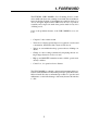
1. FOREWORD The FURUNO CSH-5 MARK-2 Color Scanning Sonar is a fullcircle,multibeam electronic scanning sonar which detects and instantaneously displays fish schools and underwater conditions in 16 colors on a 14" non-glare, high resolution CRT screen. Its ease of operation, versatility and compact size make it the perfect match for any class of fishing vessel.
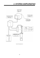
2.
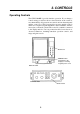
3. CONTROLS Operating Controls The CSH-5 MARK-2 provides intuitive operation. If you change a control setting you will see the associated reaction on the screen almost immediately. All operations are carried out from the main panel and the control box. The front panel incorporates mainly controls which do not require frequent adjustment, such as brilliance, interference rejector, and audio volume.
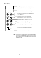
Main Panel AGC suppresses the echo tail of strong targets, e.g., the seabed, for easy recognition of fish schools adjacent to the sea bottom. Position "1" or "2" is the normal setting. NOISE LIM is used to reject noise which is displayed over the screen in light blue. Position "3" is the normal setting. 4 4 6 8 2 8 2 10 0 1 6 10 0 AGC NOISE LIM 2 2 1 3 IR (Interference Rejector) rejects random noise and interference caused by other echo sounders or sonars.
Control Box Panel TRANSDUCER retracts and lower the transducer. The lamp above the switch flickers while the transducer is moving and lights when stopped. TX turns on the transmitter, freeze the display and turns off the transmitter. The light above the switch is on when the transmitter is turned on and flickers when off. Note: The transmitter is turned off when the transducer is retracted even if the light above the TX switch is on. MENU turns the menu display on and off.
EVENT EVENT DELETE R/B F1 EVENT displays the latest event mark “ + ” and its position data; i.e., horizontal range, depth and bearing measured from own ship’s position. (optional interface board is required to use this function.) To delete event mark, locate the cursor on a event mark you want to delete and press EVENT DELETE key. R/B draws a straight line, called Bearing Mark, from own ship position mark “ ” toward the trackball mark “ ” and simultaneously to .
Menu Screen The CSH-5 MARK-2 employs four menu screens; menu-l, menu-2 and system menu. Of the four menus, the menu-2 and system menu contain preset items which do not require setting alteration if they are once set at installation. See page 32 for further details. The menu-l contains items to be set by the operator while using the sonar, taking the fishing ground and fishing method into account. This menu can be recalled on the lower part of the screen as “scan menu” during normal operation.
Turning Off Scan Menu To turn off the scan menu, press the MENU key. Note: Settings for the items shown in red are locked. To unlock the settings, call up the system menu. See page 33.
Sets the scan width; ±10, ±20, ±40 or ±60 (in degrees). Use a wide width to conduct a general search of a scan area, narrowing it once a fish school is detected. AUTO TILT WIDTH This menu is used to set the automatic tilt width (in degrees); ±2 - ±10, ±4 - ±14, ±6 - ±20, or ±10 - ±26. The two numbers in each setting shows that the width changes as the range in use changes; left number for the longest range and right one for the shortest range.
4. BASIC OPERATION General This section provides information necessary for basic operation of the CSH-5 MARK-2, from turning the power on and off to detecting and tracking fish schools. The basic operating procedure is shown below. Basic Operating Procedure CONTROL SETTINGS Location for magnetic function card OUTPUT PL TVG, (Far, Near) AGC NOISE LIM VP IR 10 10 5, 5 0 3 1 OFF 1/8 Turn power ON (OFF). 2/7 Lower/raise transducer. 4 Turn transmitter on. 5 Set tilt angle. 6 Adjust gain.
Power Off Press the TRANSDUCER “ ” switch on the control box. Wait until the lamp above the switch lights, and then press the POWER “OFF” switch. Note that the transducer automatically retracts into the tank even if the POWER “OFF” switch is pressed without raising the transducer (by pressing the TRANSDUCER “ ” switch). However, for safety purposes, it is recommended that you make a habit of pressing the TRANSDUCER “ ” switch first to ensure that the transducer is retracted.
Seabed Echo vs Tilt Angle Case 1: Tilt Angle 30 to 40 degrees A wide tilt angle will display the entire seabed since it is captured by the full width of the beam. Case 2: Tilt Angle 10 to 20 degrees A narrow tilt angle will display only half the seabed since it is captured by only the lower half of the beam. Case 3: Tilt Angle 0 to 10 degrees An exceptionally narrow tilt angle may or may not capture the seabed since the returning echo is weak.
Points to Consider • As a general rule of thumb, a vertically distributed fish school is a better sonar target than the seabed, since it reflects the transmitted pulse back toward to the source. • In case 3, both fish schools a and b are presented. Generally speaking, however, midwater fish schools tend to be larger than bottom fish schools and they are often displayed near the seabed on the sonar screen. • Detection of bottom fish is difficult if they are not distributed vertically.
m Depth 14 100 (200) 13° 23m 100m 46m 200m 200 (400) Tilt angle vs.
Adjusting the Gain The gain should be adjusted to see fish echoes clearly with minimal noise on the screen. Too high a setting not only causes excessive noise on the screen and makes it difficult to discriminate wanted fish echoes but also causes seabed echoes to be painted in strong colors, resulting that the echoes from bottom fish are masked by seabed reflections. Normally, positions “3” thru “7” are used.
5. FINE TUNING THE PICTURE General In the previous chapter basic operation of the sonar was presented. This chapter describes the procedures for fine tuning the sonar picture. Eliminating Unwanted Feeble Echoes Echoes from targets such as seabed and fish return to the transducer in order of distance to them, and when we compare their intensities at the transducer face, those from nearer targets are generally stronger when their reflecting properties are nearly equal.
3. Locate a fish school on a long range setting which is approaching own ship. Note that the tilt should be kept adjusted so that the fish school is always placed in the center of the sonar beam, i.e., so that the fish school is displayed in strongest colors possible. Check that the fish echo is displayed in the same color while it approaches. If the color changes suddenly to weaker colors as the fish echo enters FAR and NEAR areas, the TVG is improperly set. Adjust the TVG in the scan menu to correct it.
Suppressing Seabed and Sea Surface Reflections in Shallow Fishing Grounds In shallow fishing grounds with hard or rocky bottom, seabed reflections often interfere with wanted fish echoes and they can not be eliminated sufficiently with the aforementioned TVG and AGC controls, especially when the TILT is set to a larger angle in order to track fish schools approaching within 400 m. In such cases try to reduce the output power by setting the OUTPUT in the scan menu without turning down the gain.
Rejecting Noise with IR Control This control is similar to the interference rejector on echo sounders and radars. It is effective for rejecting random noise and sea surface reflections in rough sea conditions. Set the IR control to positions “1” thru “3” so that noise is just eliminated. Do not use an unnecessarily high setting since it may also reject small wanted echoes.
6. ADVANCED OPERATION General It this section, how to use the CSH-5 MARK-2 effectively in actual fishing operations is presented. Measuring Range and Bearing to a Target To measure the range and bearing to a target, use the trackball. Procedure 1. Operate the trackball to place the trackball mark “ ” on the target you want to measure the range and bearing. The range and bearing are displayed at the left top on the screen.
Procedure 1. Move the trackball mark “ ” to the direction you want to monitor through the speaker, by operating the trackball. 2. Press the R/B key. The bearing marker will appear in the direction of the trackball mark and echoes in that direction are monitored through the speaker. Adjust the volume with the AUDIO control on the front panel. To cover a certain area, press the SECTOR SCAN key.
2. Press the OFF-CENTER key on the front panel. 3. To move the own ship mark back to the center of the screen, press the OFF-CENTER key again. Finding Fish School Center When you want to find the center depth of a fish school, use the auto tilt function which automatically scans the tilt angle within the selected width. Procedure 1. Call up the scan menu, select the menu item “AUTO TLT WDTH” and then choose a tilting width. The center tilt angle of the scanning is set by the TILT lever.
Registering Procedure 1. Press the MENU key. 2. Rotate the RANGE control to select FUNC KEY PROG. 3. Rotate the GAIN control to select FUNC1 or FUNC2. 4. Press the TX key. Each time the TX key is pressed, the current settings in the scan menu and E/S menu are recorded. When FACTORY is selected, the default value is displayed. Recalling Procedure 1. Press F1 or F2. Presetting function is recalled and function indication (LED lamp) lights. Canceling the recalling 1. Press F1 or F2 again.
7. MARK AND DATA This chapter describes the marks and data which appear on the display screen. TRACKBALL MARK DATA Slant Range Horizontal Range Depth True Bearing G . RANGE TILT AUTO TILT GAIN BEARING MARK RANGE MARK TRACKBALL MARK HEADING MARK OWN SHIP MARK RANGE RING BEARING OF BEARING MARK RANGE TO RANGE MARK Marks Own Ship Mark Trackball Mark Heading Mark Shows ship's position on the screen. The mark points in the direction of ship's heading.
Range Ring Range/Bearing Marks The range rings are plotted at intervals of 1/4 of the range in use. Range ring data are also provided every two range rings. The range ring interval can be altered from 1/4 to 1/2 of the range in use by changing the appropriate setting on scan menu. The range and bearing marks are displayed when the R/B key is pressed and the bearing mark scans in a few degree steps when the SECTOR SCAN key is pressed, giving audio in that direction.
8. INTERPRETING THE DISPLAY General This section provides information necessary for interpreting the display. Interpreting the Display Seabed When the tilt angle is changed, the seabed echo illustrated below will appear on the screen. When the tilt angle is decreased, the seabed trace becomes wider and weaker. By observing the seabed condition on the screen, the skipper can prevent the net from being damaged by a reef or a shipwreck.
Fish School A fish school appears as a mass of echoes on the screen. The color of the mass shows the density of fish schools on the sonar beam. To know the distribution and center point of a fish school, the tilt should be changed to several different angles. (a) Sea Surface Fish Tilt Angle: +5° - 10° Fish school Sea Surface Reflections Because of the narrow tilt angle, seabed echo is not displayed. Sea surface reflections are present.
Sea Surface Reflections To reduce the sea surface reflections, set the tilt angle to 5° or more so that the upper edge of the sonar beam may not hit sea surface, or adjust TVG functions. When the sonar is used with a narrow tilt angle, the sea surface reflections cover large area (up to 300 m to 400 m) as illustrated below.
False Echo by Sidelobe In the preceding chapters, it was explained that an ultrasonic wave is emitted only in the direction set by the TILT lever, but, in practice, there are some emissions outside the main beam that are called “sidelobes”. Energy of the sidelobe is fairly weak but when the sonar is used in comparatively shallow water with a hard and rocky bottom, strong target signals are detected by the sidelobe. These are represented on the screen as a false echo as shown below.
9. WARNING Overvoltage Warning If the supply voltage rises about 20% to over the rated value, the overvoltage detection circuit is actuated. The following warning flickers at the center of the screen and an alarm sounds. OVERVOLTAGE! If this occurs, retract the transducer, turn the POWER off and check the ship’s mains (and the stepdown transformer if provided).
Hand Crank Power LED (Green) Down Command LED (Red) Bottom Power SW Breaker ON hull unit OFF Power switch (Normally " " position) Main Fuse Fuse for Transceiver Transceiver Unit 31
10. MENU General The CSH-5 MARK-2 employs three menu screens, menu-1 menu-2, and system menu, to preset infrequently used functions. Changing Menu Settings Procedure to Change Menu Settings 1. Turn off the transmitter with the TX key; LED flickers. 2. Press the MENU key. The menu-1 appears. 3. To select another menu, operate the GAIN control. 4. Select a menu item with the RANGE switch and change the setting with the GAIN control. Note: Setting for the items shown in red are locked.
Menu-2 The figure below shows menu-2. ** MENU 2 ** MENU MODE : MENU-1 EXT KP RANGE MARKER MARK INDI MENU MENU MODE EXTernal Keying Pulse RANGE MARKER MARK INDI OFF 1/4R ±180° MENU-2 SYSTEM ON 1/2R 360° OFF MEANING Selects a menu: menu-l. menu-2. system menu. If two or more echosounders/sonars are operated simultaneously, mutual interference may result due to asynchronous keying pulse output. This menu is used to synchronize keying pulses/turn off synchronization.
MENU ITEM MENU MODE HEADING ADJ AUTO SCAN SPD AUTO TILT SPD UNIT MENU SELECT SUB TEXT INDIcation LANGUAGE SELF TEST MEANING Selects a menu; menu-1, menu-2, system menu. This menu is used to compensate for hull unit misalignment, which results in heading error. Set the actual heading by operating the GAIN control so that the own ship's wake is displayed in 180° direction on the screen. Selects the scan speed of bearing marker; high or low.
11. INTERFACE MODULE CSH-5060 Specifications The CSH-5060 Interface Module permits connection of external equipment (navigational equipment, current indicator, echo sounder, net sonde, gyrocompass, log, etc.) to display various data on the CSH-5 MARK-2. 1. Display Mode (a) Normal (b) Normal + Text (c) Echo Sounder Combination (Normal + Echo Sounder) (d) Sonar Combination (Normal + Signal on R/B Mark) 9/10 3/5 3/5 2/5 2/5 1/10 (a) (b) (c) (d) 2.
Operation The functions of the Interface Module are accessed from the MENU screen except the Event mark and North mark*. * —Gyrocompass required. 1. Event Mark and Own Ship Mark Plotting (1) Move the cursor to the location where you want to plot the event mark. (2) Press the EVENT key. The cursor is replaced with the latest event mark [ ] and the event mark data (horizontal distance, depth and bearing) appears on the lower left side of the screen.
TARGET LOCK FUNCTION θ1 θ2 D The target lock function allows continuous tracking at a present depth "D". That is, the tilt angle changes automatically from "θ1" to "θ2" as the ship approaches the fish. 3. Erasing Weak Noise Unknown weak noise appearing over the entire screen can be erased with DELETE COLOR, on the SCAN menu. Echoes are erased in order from weakest to strongest, so you may use this function to show only strong echoes. 1. Press the [MENU] key to turn on the menu. 2.
4. Suppressing Effects of Pitching and Rolling The Motion Sensor MS-100 (option) compensates for the effects of pitching and rolling to provide stable sonar pictures. You may enable it as follows: 1. Press the [MENU] key to display the SCAN menu. 2. Use the RANGE control to select RANGE/BEARING. 3. Use the GAIN control to select STAB. 4. Press the [MENU] key to close the menu. 5. Operate the trackball to place the trackball mark on the bearing you want to compensate by the MS-100. 6. Press the [R/B] key.
5. Detecting Fish Echoes in Specific Area (Fish Alarm) The fish alarm alerts you to fish echoes in an area you select. Any fish echoes entering the area will trigger the audio alarm. The fish echo level which triggers the alarm may be selected from the scan menu. 1. Press the [MENU] key to open the SCAN menu. 2. On the scan menu, use the RANGE control to select RANGE/ BEARING. 3. Use the GAIN control to select FISH/ALM. 4. Use the RANGE control to select FISH ALARM. 5. Use the GAIN control to select ON. 6.
6. Fish Alarm On/Off, Fish Alarm Sensitivity The audio alarm for the fish alarm can be enabled/disabled and the fish alarm sensitivity can be selected from the scan menu. 1. Press the [MENU] key to open the SCAN menu. 2. Use the RANGE control to select FISH ALARM. 3. Use the GAIN control to select the echo strength which will trigger the fish alarm. The setting range is 0 to 14. Choose "0" for no audio alarm.
8. Menu Description The CSH-5 MARK-2 employs three menu screens, MENU-1, MENU2 and SYSTEM Menu, to preset infrequently used functions. During normal operation (transducer lowered, transmitter ON), the SCAN Menu appears on the screen. This lets you adjust settings while observing the sonar picture. Application MENU-1 MENU-2 SYSTEM MENU For system setting SCAN MENU For user setting E/S MENU How to use After installation, select each item according to your system configuration.
MENU-2 ** MENU-2 ** ( RANGE SW : U/D GAIN SW : L/R ) [MENU MODE] : MENU-1 MENU-2 EXT KP SYNC RANGE MARKER BEARING SCALE CURRENT MARK COURSE MARK HEADING INDI CURRENT INDI EVENT INDI MARK INDI POSITION DATA : : : : : : : : : : ON 1/2R OFF OFF 5R TRUE TRUE TRUE 360° TD OFF 1/4R ON ON 10R 32-AZI 32-AZI 32-AZI ±180° L/L SYSTEM OFF OFF ±180° ±180° 360° 360° SYSTEM MENU ** SYSTEM MENU ** [MENU MODE] : MENU-1 HEADING ADJ AUTO SCN SPD AUTO TLT SPD UNIT SHIP’S SPD/BR LOG PULSE CI BAUD RATE NAV FORMAT
SCAN MENU ** SCAN MENU ** ( RANGE SW : U/D GAIN SW : L/R ) MENU MODE : SCAN E/S DISPLAY MODE HUE TX OUTPUT PULSELENGTH TX CYCLE TVG NEAR TVG FAR DELETE COLOR AUTO SCN WDTH AUTO TLT WDTH MARK ERASE RANGE/BEARING FISH ALARM ALARM LEVEL HOR BEAM ANGL VER BEAM ANGL RES COL CURVE COL EMPHASIS FUNC KEY PROG : : : : : : : : : : : : : : : : : : : NORM 2 TEXT 3 COMBI-2 4 ±20° ±4~14° SHIP TARGET OFFF ±40° ±6~20° EVENT STAB.
10. Contents of Menu Items This section describes the menu items available with the addition of the CSH-5060 and external equipment. MENU-1 (SCAN, E/S Menu) Scan menu Item MENU MODE DISPLAY MODE Contents Selects a menu; MENU-1, MENU-2 or SYSTEM Menu. Selects a picture display mode among the four below.
E/S Menu Item E/S SHIFT Contents Shifts the start depth of the display range and the maximum value is about 1000 m irrespective of the depth unit. The unit shift value is determined by the range in use. See table below. 1 2 3 4 5 6 7 M 10 20 40 50 50 100 100 FT 25 50 100 100 200 200 300 FA 5 10 20 25 40 50 50 P/B 5 10 20 25 40 50 50 E/S IR E/S GAIN E/S CLUTTER E/S ADVANCE Turns the Interference Rejector on and off. Controls the gain of the Echo Sounder picture.
MENU-2 (Refer to pages 47 to 51 for location on the screen.) Item BEARING SCALE CURRENT MARK COURSE MARK HEADING INDI CURRENT INDI EVENT IND MARK INDI POSITION DATA Contents This menu turns the electronic bearing scale on and off. This menu turns the current mark on and off. This menu selects the length of the course line plot from 10R or 5R (R: range in use). If course line display is not necessary, select "OFF" to erase it. Selects 32-azimuth or true bearing indication.
Indications 1.
2.
3.
4.
Marks and Data This section explains the Marks and Data available from the equipment interfaced. Pages 24 to 25 show the location of these Marks and Data. Description New Marks and Data Latest Event Mark Data ( ) ° B Own Ship’s Mark Elecrtonic Bearing Scale W N The position data of the latest event mark, i.e., horizontal range (→), present depth (↓) and bearing. ( ) shows the latest event mark original depth which remains unchanged even if ship moves or tilt angle is changed.
Event Mark Position Output Connected to a navigator, the CSH-5 MARK-2 can output event mark position data to external equipment when the [EVENT] key is operated. The data sentence output is "SSTLL" (NMEA, IEC-1162 format).
12. MAINTENANCE General The CSH-5 MARK-2 is designed and constructed to provide many years of trouble-free performance when properly maintained. Userperformable maintenance and important points to be observed are outlined in the figure below. WARNING Do not open the cover of the equipment. Handle with care! This equipment uses high voltage electricity which can shock, burn, or cause death. Only qualified personnel should work inside the equipment.
13. UNIT DIAGNOSTIC TESTS This unit has eight built-in diagnostic tests which check it for proper performance. Although the tests are designed primarily for use by the service technician, they can also be executed by the user to identify defective components. However, never attempt to check inside the unit; there are no user-serviceable parts inside. Any repair work is best left to a qualified technician. Turning-on/off Diagnostic Test 1.
Conti Test This is a continuous test of the Display and Transceiver Units. Additionally checked devices are DROM and DRAM. CONTI TEST MAIN 105-0541-XXX 105-0542-XXX ROM = OK RAM = OK P.W = OK DROM = OK DRAM = OK DPRAM = OK TRX 105-∗∗∗∗-XXX 105-∗∗∗∗-XXX ROM = OK RAM = OK DROM = OK I/F 105-0267-XXX ROM = OK RAM = OK DPRAM = OK GYRO = OK LOG = OK ∗∗∗∗: 0635 e 107kHz 0644 e 85kHz Not displayed if interface module CSH-5060 is not provided.
Color Test The color test checks for proper display of all colors. COLOR TEST 16 Color display WHT RED GRN PRESS [MENU] 2 or 3 SECONDS TO STOP SELFCHECK Echo-1 Test The echo-1 test checks echo processing circuits in the display unit for proper operation. DISPLAY ECHO TEST R400 T10° → 240 → 236 ↓ 41 B 281° G3.
Gray Test The gray test checks for proper display of monochrome characters and markers. Concentric rings and a monochrome test bar are displayed. GRAY TEST ............ PRESS [MENU] 2 or 3 SECONDS TO STOP SELFCHECK Echo-2 Test The echo-2 test checks echo processing circuits in the transceiver and display units. PRESS [MENU] 2 or 3 SECONDS TO STOP SELFCHECK Set the VP control on the main panel to "OFF" position. Radial pattern as above is displayed.
14. CHARACTERISTICS OF THE ULTRASONIC WAVE IN WATER The purpose of this chapter is to provide an overview of the characteristics of the ultrasonic wave in water. Sound Velocity It is generally known that an ultrasonic wave travels 1500 meters per second in sea water, but in practice, some amount of variation arises depending on the season and area from differences in the following three factors: Water temperature .............................. θ [ C] Salinity density ...................................
Research in the waters throughout the world has revealed that there is a difference of approximately 100 m/s between the areas where the velocity is maximum and minimum Generally, the velocity increases as follows, provided that salinity density is constant: • 3 m/s for every 1 degree rise of water temperature • 1.7 m/s for every 100 m increase of water depth Absorption and Attenuation An ultrasonic wave emitted into water becomes weaker in intensity as it goes away from the emitting source.
Refraction An ultrasonic wave transmitted in water does not travel straight but is more or less refracted. This refraction is caused by the variation of propagation velocity in water. If the velocity decreases (temperature decreases) with depth, the top part of the wave front moves faster than its bottom part, and gradually the front bends downwards. In the same way, it bends upwards if the sound velocity increases (temperature rises) with depth. 50 16° 100 (m) 0.5 1 1.
The drawing below shows how temperature variation affects sound propagation with respect to different emitting directions (tilt angles). Beams tilted five and ten degrees bend upward at 400 m and 600 m points respectively. Beams tilted down more than 15 degrees travel in almost straight lines. Between the two beams, a blind zone is created beyond the 600 m point. In this zone nothing can be detected.
The product of the density (P) and the velocity (C) is called intrinsic acoustic impedance and in the boundary between two media which has extremely different C from each other, most of the acoustic power is reflected and only a small portion penetrates. (In the boundary between water and air, the acoustic energy penetrates with a loss of approximately 30 dB, that is approximately 0.1 % of the energy penetrates from one medium to the other.
Reflection Loss (dB) Reflection Loss (dB) Frequency (kHz) Frequency (kHz) Reflection Loss (Mackerel No.1) Species Sardine Bonito Horse Mackerel Sea Bream Turbot Average Reflection Loss (Mackerel No.2) Incident Direction of Ultrasonic Wave Back Side Head 1 1 0.8-1.2 0.9 1 63 2 2 1.4-2.2 3 2 2 0.13 0.5 0.4-0.6 0.45 0.
SPECIFICATIONS 1. Display PPI display on 14" non-glare, high resolution color CRT 2. Display Color 16 colors according to echo strength 3. Numeric information Scanning Data Trackball Mark Data Range/Bearing Mark Data (Range, Tilt angle, Gain) (Slant range, Horizontal range, Depth, Bearing) (Range, Bearing) 4.
5. AUDIO SEARCH Searching Method Echoes in the direction of the bearing mark are audibly monitored by the built-in loudspeaker. Audio Sector 20˚, 40˚, 80˚, 120˚ (selectable) Audio Output 2W Audio Frequency 800Hz 6. Transmitter/Receiver Transmitter High power MOS FET amplifier with 11-step power reduction switch Receiver Low noise superheterodyne, continuously scanning beam forming Tx Frequency 55kHz or 68kHz 7. Tilt Angle Tilt Angle 0˚ to 55˚ Auto Tilt ±2˚ to ±26˚ selectable 8.
INDEX A Absorption 59 AGC control 17 Air bubbles 61 Attenuation 59 AUDIO control 21 AUTO TILT key 6 C Color test 56 Conti test 55 Control box panel 5 D Data description 25 DEMAG button 3 Diagnostics color test 56 conti test 55 echo-1 test 56 echo-2 test 57 gray test 57 panel test 55 single test 54 SIO test 55 turning on/off 54 E event mark 36 indications 47-50 marks and data 51 menu description 41-43 menu screen 40 MENU-1 41 MENU-2 42 numeric information 35 operation 36–46 own ship mark 36 SCAN menu 43
S Scan menu 8 Sea surface reflections 28 Seabed echo 26 SECTOR SCAN key 6, 21 Sidelobe 29 Single test 54 SIO test 51 Sound velocity 58 System configuration 2 System menu 33 T Tilt angle and discriminating fish echoes from bottom 12 for surface fish 13 general selection 11 TILT lever 5, 11 Trackball 5 TRANSDUCER switch 5, 11, 30 TVG adjustment 16 TX cycle 19 W Wake recognition 28 Index-2