COLOR SCANNING SONAR MODEL CSH-7
c FURUNO E L E C T R I C C O., L TD. Your Local Agent/Dealer 9-52, Ashihara-cho, Nishinomiya, Japan 662 Telephone: Telefax: 0798-65-2111 0798-65-4200 FIRST EDITION : MAY 1997 All rights reserved. Printed in Japan PUB. No.
SAFETY INSTRUCTIONS WARNING CAUTION Do not open the equipment. Use the proper fuse. Hazardous voltage which can cause electrical shock, burn or serious injury exists inside the equipment. Only qualified personnel should work inside the equipment. Use of a wrong fuse can result in fire or permanent equipment damage. Do not use the equipment for other than its intended purpose. Do not disassemble or modify the equipment.
TABLE OF CONTENTS FOREWORD A Word to CSH-7 Owners ........................................................................................................ v Features..................................................................................................................................... v System Configuration .............................................................................................................. vi OPERATIONAL OVERVIEW Equipment Overview ...................................
INTERPRETING THE DISPLAY Seabed Echoes .......................................................................................................................6-1 Fish Schools ...........................................................................................................................6-2 Sea Surface Reflections ......................................................................................................... 6-3 Wake .......................................................................
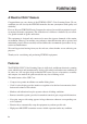
FOREWORD A Word to CSH-7 Owners Congratulations on your choice of the FURUNO CSH-7 Color Scanning Sonar. We are confident you will see why the FURUNO name has become synonymous with quality and reliability. For over 40 years FURUNO Electric Company has enjoyed an enviable reputation for quality marine electronics equipment. This dedication to excellence is furthered by our extensive global network of agents and dealers.
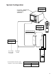
System Configuration DISPLAY UNIT CSH-7010 NAVIGATOR CURRENT INDICATOR GYROCOMPASS SPEED LOG (*) TILT REMOTE CONTROLLER RANGE GAIN CSH-7040 (Option) TRANSCEIVER UNIT CSH-7020 RECTIFIER RU-3424 (Option) 100-115 VAC/ 200-230 VAC 1φ, 50/60 Hz Ship’s Mains 24 VDC * Interface Module CSH-7050 (option) required to connect external equipment.
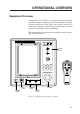
OPERATIONAL OVERVIEW Equipment Overview All operations of the CSH-7 are carried out through the display unit and the remote controller (option). The uncluttered, straightforward control panel of the display unit provides intuitive operation. If you change a control setting you will see the associated reaction on the display almost immediately. The handy remote controller provides armchair control of range, gain and tilt functions.
Display Unit Control Panel Description Raises, lowers the transducer, respectively. Lamp above a key blinks while the transducer is moving and lights when it stops. d c – TX Turns transmitter on/off; freezes the display. The lamp above the switch lights when the transmitter is turned on and flickers when off. + Selects a picture display range. Also functions to select items on menu screens. Note that this control turns endlessly in both directions. RANGE – + Adjusts receiver sensitivity.
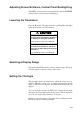
Adjusting Screen Brilliance, Control Panel Backlighting The BRILL control adjusts screen brilliance, and the DIMMER control adjusts control panel backlighting. Lowering the Transducer Press the d switch. The lamp above the switch blinks, and lights when the transducer is fully lowered. CAUTION Do not exceed speed noted in the specifications when operating the equipment or lowering or raising the transducer. The transducer may become damaged.
Seabed echo and tilt angle Case 1: Tilt angle 30 to 40 degrees This tilt angle will display the entire seabed since it is captured by the full width of the beam. Case 2: Tilt angle 10 to 20 degrees This tilt angle will only display half the seabed since it is only captured by the lower half of the beam. Case 3: Tilt angle 0 to 10 degrees This tilt angle may or may not capture the seabed since the returning echo is weak.
Points to consider • Normally, a vertically distributed fish school is a better sonar target than the seabed, because it reflects the transmitted pulse back toward the transducer. • In case 3, both fish schools a and b are presented. Generally speaking, however, midwater fish schools tend to be larger than bottom fish schools and they are often displayed near the seabed on the display. • It is difficult to detect bottom fish when they are not distributed vertically.
Suitable tilt angle The figure below illustrates the relationship among tilt angle, depth and detection range. Refer to it to find out the suitable tilt angle for a given depth/detection range.
Adjusting the Gain The GAIN control adjusts receiver sensitivity (gain). Adjust it so fish echoes are clearly displayed with minimal noise on the screen. Too high a setting not only displays excess noise and makes it difficult to discriminate wanted echoes but also causes seabed echoes to be painted in strong colors, resulting in echoes being masked by seabed reflections. Normally, set the control somewhere between positions “3” and “7”.
MARKERS AND DATA Standard Markers and Data Heading data (Requires INTERFACE Board and gyrocompass.
Table 2-1 Standard markers and data description Marker/Data Description Marks position on the screen. Direction of arrow is heading. Trackball Marker The trackball marker selects location for markers and own ship’s position. The trackball moves the marker over the entire screen. Trackball Data Trackball data: : Slant range → : Horizontal range ↓ : Depth B : Bearing → → Own Ship Marker → ↓ B ° Bearing is shown in 360¡ or –180¡ indication system, relative to ship’s heading.
Optional Markers and Data Various markers and data are available with connection of the INTERFACE Board and appropriate external equipment. Optional markers and data in the normal mode Heading indication E/N Trackball marker data B R 300 T 5° 187 186 16 23°S E G 3.
Optional markers and data in the normal plus text mode Heading indication NW/N R 800T T 5° 496 493 51 52°S B G 4.0 N Latest event marker W 3 2 Past event marker 1 Latest event marker data Nav data 367 38 ( 165) B 283° S C D T 0.0 NW/W 174 17.0 S R 313 B 34: 13.02N 135: 16.39E C1: 1.1 315° C2: 0.6 25° C3: 1.
Table 2-2 Optional markers and data description Marker Description Latest Event Marker Data → ↓ ( B ) ° The position data of the latest event marker, that is, horizontal range (→), current depth (↓) and bearing. ( ) shows the latest event marker’s original depth, and remains unchanged regardless of ship’s movement or tilt angle. When the event marker is erased the above data disappears from the screen. To erase an event maker, place the trackball maker on the event marker and press the EVENT key.
MENU OVERVIEW The menu system consists of four menus: Scan menu, Menu-1, Menu-2, and System. The Scan menu can be opened while transmitting, and contains items which the user will often change during the course of operation. Menu-1 (similar to the Scan menu), Menu-2 and System menus can be opened with the transmitter turned off. Menu-2 and the System menus contain items which once set do not require frequent adjustment. Scan Menu Operation Displaying the scan menu 1.
3. Operate the RANGE control to scroll the menu and select item. The selected item is highlighted in green and current setting in white. 4. Operate the GAIN control to change setting. 5. Press the MENU key to register selections and close the menu. Note: Gain or range cannot be changed while the Scan menu is displayed. Scan menu description Table 3-1 Scan menu description 3-2 Item Description DEGAUSS Enables degaussing of the screen by pressing the TX key on the menu screen.
Table 3-1 Scan menu description (con’t.) Item Description IR Rejects random noise and interference caused by other echo sounders or sonars. MARK ERASE Erases all own ship markers or course line. HOR BEAM ANGL Selects horizontal beam angle. Select wide for general use; narrrow for better bearing discrimination. RES COLOR CURVE Sets the balance between weak and strong echoes. LINEAR varies output proportionally with input (actual echo strength).
Displaying menu-1, menu-2, system menu 1. Press the TX switch to blink the lamp (transmitter off state) above it, if it is not already blinking. 2. Press the MENU key. The last-used menu among Menu-1, Menu-2, and System appears. The menu below is Menu-1.
This menu contains the same items as the Scan menu. See page 3-2 for description.
System menu description ** SYSTEM MENU ** MENU MODE : MENU - 1 # HEADING ADJ : 0° # UNIT # SHIP’S SPD/BR # # (RANGE SW: U/D GAIN SW: L/R) MENU - 2 SYSTEM : METERS FEET FATHOMS : LOG/GY CI NAV LOG PULSE : 200 400 CI BAUD RATE : 4800 2400 1200 # NAV FORMAT : CIF NMEA183 NMEA182 # NAV BAUD RATE : 4800 2400 1200 # NAV DATA : GPS LC DEC DR : LA ALL MENU SELECT : LOCK UNLOCK # SUB TEXT INDI : OFF ON # LANGUAGE : ENGLISH SELF TEST : SINGLE CONTI DEFAULTS PA/B
FINE TUNING THE PICTURE Eliminating Unwanted Feeble Echoes Echoes from targets such as seabed and fish return to the transducer in order of distance to them, and when we compare their intensities at the transducer face, those from nearer targets are generally stronger when their reflecting properties are nearly equal.
4. Locate a fish school on a long range setting which is approaching own ship. Adjust the tilt to keep the fish school in the center of the sonar beam, namely, fish school is displayed in strongest colors possible. Confirm that the fish echo is displayed in the same color as it approaches. If the color suddenly changes to weaker colors as the fish enters FAR and NEAR areas, the TVG is improperly set. Adjust the TVG.
fish echoes from seabed reflections. Decrease the PULSELENGTH setting on the Scan menu to shorten the pulselength. For search of surface and midwater fish in which seabed reflections are not so strong, use the longest pulselength “10”.
Rejecting Sonar Interference and Noise While observing the sonar picture, you may encounter occasional or intermittent noise and interference. These are mostly caused by on-board electronic equipment, engine or propeller noise, or electrical noise from other sonars being operated nearby. Identifying noise source To eliminate noise effectively, you should first identify the noise source as follows: 1. Turn off the TX switch and operate all on-board equipment one by one while observing the picture. 2.
Rejecting interference with TX cycle When other sonars operate nearby at the same transmission interval as that of own ship’s sonar, an interference ring caused by other sonars is displayed. To erase the interference ring from the screen, reduce the TX CYCLE setting on the Scan menu.
ADVANCED OPERATION Measuring the Range and Bearing to a Target Operate the trackball to place the trackball marker (+) on the target you want to measure the range and bearing. The range and bearing are displayed at the top left corner on the screen. Trackball marker Slant range Horizontal range Depth Bearing B Figure 5-1 Location of range and bearing indications Note: The bearing is shown in either 360° or 180° indication system relative to the ship’s heading.
Trackball marker Bearing marker Figure 5-2 Area monitored in audio function (sample) Relocating Fish School for Easy Observation When a fish school is located near the edge of the screen and inconvenient for observation, use the off-center function to relocate the fish school to the desired place on the screen. Fish echo Fish echo OFF CENTER key turned on Trackball marker Own ship Figure 5-3 Off-center function 1. Move the trackball marker to the position where the own ship mark is to be moved. 2.
Function Keys (F1, F2) Function keys F1 and F2 work like the auto dialing feature on a telephone, instantly calling out desired settings to perform specially assigned functions. These keys provide optimum sonar settings for a specific purpose with a single key operation. Each function key can be assigned a combination of particular sonar settings which will be most suited to a specific objective, for example, detection of a fish school.
Programming user programs 1. Press the TX switch to blink the lamp above it, if it is not already blinking. 2. Press the MENU key and select Menu-1. 3. Using the RANGE and GAIN controls, set menu options as desired. 4. Operate the RANGE control to select USER PROG. 5. Operate the GAIN control to select USER1 (for F1 key) or USER2 (for F2 key). 6. Press the TX key to register the settings. 7. Press the MENU key to register settings and close the menu.
Event Markers, Own Ship Event Markers The event marker denotes important items on the display, such as a fish school, and the own ship event marker marks own ship position. Ten event markers and ten own ship event markers may be entered. The CSH-7 denotes the latest event marker as and other event markers as +. The own ship event marker is a triangle .When more than ten of either marker is entered the eldest corresponding marker is erased to make room for the latest.
INTERPRETING THE DISPLAY Seabed Echoes When the tilt angle is widened, the seabed echo illustrated below will appear on the display. When the tilt is narrowed, the seabed trace becomes wider and weaker. By observing the seabed condition on the display, the skipper can prevent net damage. (A) Flat seabed Tilt angle: 10° to 15° Narrow tilt angle Only half of vertical beam width captures the seabed.
Fish Schools A fish school appears as a mass of echoes on the screen. The color of the mass shows the density of fish schools on the sonar beam. To find distribution and center point of a fish school, try several different tilt angles. (A) Sea surface fish Tilt angle: -5° to 10° Fish school Seabed echo not displayed because of narrow tilt angle. Sea surface reflections are present.
Sea Surface Reflections To reduce sea surface reflections, set the tilt angle to 5° or higher, so the upper edge of the sonar beam does not hit the sea surface, or adjust TVG. When a narrow tilt angle is used, sea surface reflections cover a large area as illustrated below.
False Echo by Sidelobe An ultrasonic wave is emitted only in the direction set by the TILT lever, however there are some emissions outside the main beam. These are called sidelobes. The ennergy of the sidelobe is fairly weak but when the water is comparatively shallow and the bottom is rocky and hard, strong signals are detected by the sidelobe. These are represented on the display as a false echo as shown below.
MAINTENANCE WARNING Do not work inside the equipment unless totally familiar with electrical circuits. Hazardous voltage which can cause electrical shock, burn or serious injury exists inside the equipment. Display Unit Maintenance Handle the equipment with care. Damage can cause corrosion. Clean the screen and filter regularly. Cover the equipment when it is not in use. An anti-static spray may be used to clean the screen. Do not use chemical-based cleaners; they can remove paint and markings.
Hull Unit Maintenance Apply MOLYTONE grease #2 every six months. Raise transducer and coat main shaft with DAPHAECOROAEX #2 every six months. CAUTION The zinc block near the transducer must be replaced yearly. The junction between the transducer and main shaft may corrode, which can result in loss of the transducer or water leakage inside the ship. HULL UNIT Figure 7-2 Hull unit maintenance 7-2 Dry dock ship and clean transducer face yearly.
TROUBLESHOOTING WARNING Do not work inside the equipment unless totally familiar with electrical circuits. Hazardous voltage which can cause electrical shock, burn or serious injury exists inside the equipment. When the Transducer Cannot be Retracted When the transducer cannot be completely retracted within 35 seconds after pressing c, XDCR NOT RETRACTED! blinks at the screen center and the alarm sounds. If this occurs do the following: 1.
Hand crank Shaft gear Motor gear CAUTION POSSIBILITY OF INJURY POWER ON/OFF LED (Green) 1. If breaker (hull unit) trips do the following: DOWN command LED (Red) 1) Turn off power swich on hull unit. 2) Wait 60 sec after breaker has tripped. 3) Press breaker. 2. Turn off hull unit before using hand crank. Breaker Cable gland Breaker ON/OFF state POWER switch Breaker 8A (Bottom view) ON OFF How to use the hand crank 1. Turn off the POWER switch on the hull unit. 2. Remove gear cover. 3.
Diagnostic Tests CAUTION Raise the transducer before conducting the diagnostic tests. In the diagnostic tests the MENU key raises the transducer. Thus, personal injury can result if the key is operated while someone is near the transducer. This unit has eight diagnostic test which check it for proper operation. These tests are mainly for use by service technicians, however the user may execute them to identify possibly defective components. Starting, quitting diagnostic tests 1. Press the MENU key. 2.
Note: When the transducer is fully lowered, pressing the MENU key at the diagnostic test raises the transducer. Panel test This test checks the control panel for proper operation. PANEL TEST 0 0 0 0 0 0 0 0 0 0 0 0 For Remote Controller (Option) Press each control one by one. Corresponding figure changes if control is normal. 0 0 0 0 X=0 0 0 0 Y=0 PRESS [MENU] 2 or 3 SECONDS TO STOP SELFCHECK Figure 8-3 Results of panel test Color test The color test checks for proper display of all colors.
Figure 8-4 Color test display Gray test This test checks for proper display of monochrome characters and markers. Concentric rings and a monochrome test bar are displayed. GRAY TEST PRESS [MENU] 2 or 3 SECONDS TO STOP SELFCHECK ..... ... Figure 8-5 Gray test display Conti test This test continuously checks the display and transceiver units. In addition to the devices checked in the single test, the DROM and DRAM are also checked. CONTI TEST MAIN 105-0557-0xx ROM = OK RAM = OK P.
Figure 8-6 Results of continuous test SIO test This text checks transceiver unit input and output. SIO TEST MAIN SIO1 I/F SIO-NAV = NG SIO-CI = NG = OK For service technicians; special test connector required to check. NG appears when no test connector is connected. PRESS [MENU] 2 or 3 SECONDS TO STOP SELFCHECK Figure 8-7 Results of SIO test Echo-1 test This test checks the echo processing circuits in the display unit for proper operation. DISPLAY ECHO TEST ª → ↓ B 240 236 41 281° R 400 T 10° G 3.
Figure 8-8 Echo-1 test display Echo-2 test This test checks echo processing circuits in the display unit and transceiver unit. TRX ECHO TEST PRESS [MENU] 2 or 3 SECONDS TO STOP SELFCHECK Figure 8-9 Echo-2 test display Note: Appearance of above test pattern may vary slightly depending on the frequency or internal settings.
SPECIFICATIONS Model CSH-7-xx (55: 55 kHz, 70: 70 kHz) Display Display PPI display on 10" non-glare high resolution CRT Display color 16 colors according to echo strength Display mode Normal, *Normal plus text Display resolution 512 x 384 dot Markers, indications Own ship marker, Heading marker, Trackball marker, *Own ship event marker, *Event marker, Unretracted transducer indication, Bearing marker, Range marker, Range rings, *Course line marker, *North marker, *Tidal current marker, *Electronic
Range, TX cycle, pulselength Range, range display Range (m) 85 100 150 200 250 300 350 400 450 500 600 800 Maximum display range (m) Off-center OFF Off-center ON 110 135 130 160 195 240 260 320 325 400 390 480 455 560 520 640 585 720 650 800 780 960 1040 1280 1. Ranges shown for off-center on are maximum. 2. Fish school may not be detected depending on its nature or sea conditions, even if it is located within the display range in use. Pulselength 0.
Tilt Angle Tilt beam angle 0° to 55°, continuously variable Hull Unit CSH-7030 CSH-7031 Transducer travel 600 mm 400 mm Raising time 25 sec 20 sec Lowering time 20 sec 14 sec Driving system Remote electric control Allowable ship's speed 18 knots max, 16 kts during raise/lower operation Power Supply, Power Consumption 24 VDC, 160 W (average), maximum 280 W (ship’s speed 16 knots, raising transducer) (100 VAC operation with optional rectifier) Color Display unit Panel: N 3.0 Newtone No.